
Ultraviolet light treatment chamber

a treatment chamber and ultraviolet light technology, applied in water/sewage treatment by ion exchange, disinfection, instruments, etc., can solve the problems of limiting the amount of dosage that can be provided, large increase, and suffer from several problems, so as to reduce the contamination of fluids, increase the effective treatment dose, and facilitate the effect of economic implementation

Active Publication Date: 2018-03-01
NEO TECH AQUA SOLUTIONS
View PDF3 Cites 4 Cited by
  • Summary
  • Abstract
  • Description
  • Claims
  • Application Information

AI Technical Summary

Benefits of technology

The present invention is about methods and devices for using ultraviolet light to treat liquids and gases. The invention offers easier and more cost-effective ways to treat contaminated fluids and gases, whether they are used for drinking water, industrial processing, or other purposes. The invention provides higher treatment doses for a given power input and can reduce or eliminate biological agents and chemicals. It also improves uniformity and flame arcs, which are important for optimal performance.

Problems solved by technology

Unfortunately, U.S. Pat. No. 4,948,980 describes approaches that significantly limit the amount of dosage that can be provided to effectively treat a liquid or gas.
For instance, U.S. Pat. No. 4,948,980 does not appreciate the use of a high reflectivity diffuse reflector to treat a liquid or gas with a low absorption cross-section nor does the patent anticipate a large increase in dose delivered to a target as the net reflectivity of the entire chamber approaches 100 percent.
Unfortunately, the approaches described in U.S. Patent Application Publication No. 2004 / 0166018 suffer from several problems.
For example, since these approaches do not attempt to increase the transparent or translucent containment volume compared to total chamber volume, the performance of the apparatus is not maximized.
In addition, the reflector used is not isolated from the medium being treated; and no option exists for replacing lamps without opening the chamber, thereby increasing the difficulty in using and maintaining the system.
However, the approaches described in this patent also suffer from several problems.
For example, the efficiency of the approaches described in U.S. Pat. No. 6,228,332 are limited, because these approaches do not use a reflective surface or substantially enclose the treatment chamber in order to treat the liquid or gas target.

Method used


Image

  • Ultraviolet light treatment chamber
  • Ultraviolet light treatment chamber
  • Ultraviolet light treatment chamber

Examples


Embodiment Construction

[0026]The following is a description that includes the best modes presently contemplated for practicing the invention. This description is not to be taken in a limiting sense, but is made merely for the purpose of describing the general principles of the invention and providing examples thereof. The scope of the present invention should be ascertained with reference to the issued claims.

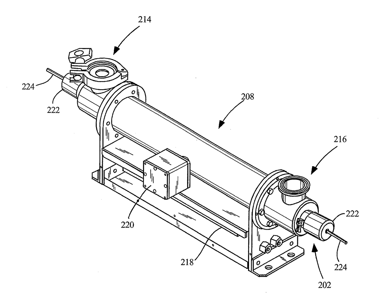
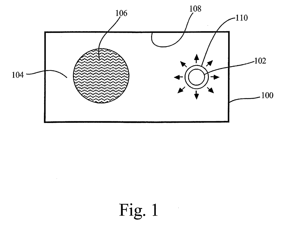
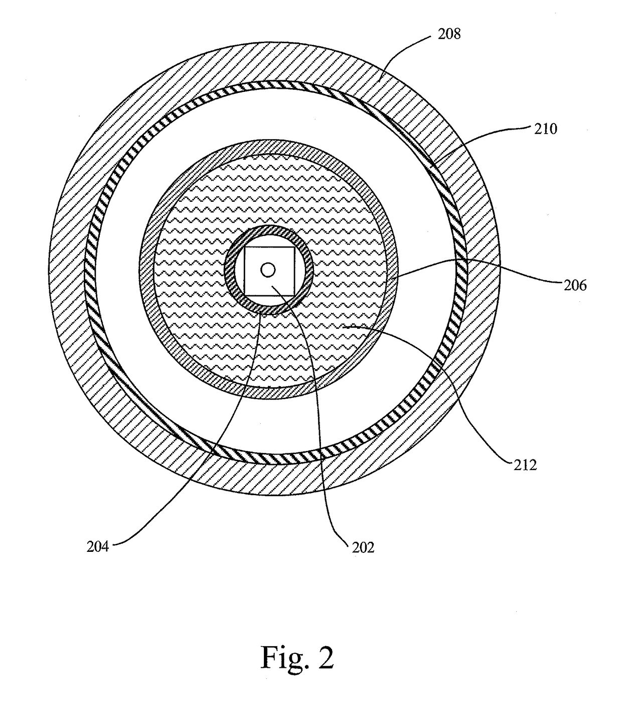
[0027]The present apparatus provides for a large reduction in the total UV power required to treat a target liquid or gas to a specified dose level. This is accomplished by enclosing the target and the UV light source within a chamber which has walls with an extremely high-reflectivity lining or coating and by minimizing the size and number of openings in the chamber wall and absorbing surfaces within the chamber. The chamber design allows for increased photon deposition resulting in enhanced UV irradiation efficiency. Synergy is achieved by combining both of these criteria, because the dose delivere...


PUM

PropertyMeasurementUnit
reflectivityaaaaaaaaaa
wavelengthsaaaaaaaaaa

Abstract

An apparatus for the treatment of a liquid that includes a chamber having at least one inner surface, the chamber adapted for passage of a fluid therethrough. The chamber is at least 80 percent enclosed. The apparatus also includes an optional ultraviolet-transmissive tube disposed within the chamber and also adapted for the passage of the liquid therethrough. The apparatus further includes an ultraviolet lamp disposed within the chamber and, optionally, within the ultraviolet-transmissive tube. A reflective material is interposed between the chamber and the transmissive tube. The reflective material is adapted so as to reflect at least a portion of light emitted by the ultraviolet lamp, wherein the reflective material is at least 80 percent reflective.

Description

CROSS-REFERENCE TO RELATED APPLICATION(S)[0001]This application is a continuation of U.S. application Ser. No. 12 / 416,075, filed Mar. 31, 2009, for ULTRAVIOLET LIGHT TREATMENT CHAMBER, which is a continuation-in-part of U.S. patent application Ser. No. 11 / 959,445 filed Dec. 18, 2007, for ULTRAVIOLET LIGHT TREATMENT CHAMBER, now U.S. Pat. No. 9,511,344, and a continuation-in-part of U.S. patent application Ser. No. 11 / 217,772 filed Aug. 31, 2005, for ULTRAVIOLET LIGHT TREATMENT CHAMBER, now U.S. Pat. No. 7,511,281, which are all incorporated in their entirety herein by reference.TECHNICAL FIELD[0002]The present invention technically relates to the treatment of fluids using ultraviolet light. More specifically, the present invention technically relates to the treatment of fluids using ultraviolet light. Even more specifically, the present invention technically relates to the treatment of fluids using ultraviolet light for deactivating microorganisms.BACKGROUND ART[0003]Various approac...

Claims


Application Information

Patent Timeline
Patent Type & Authority Applications(United States)
IPC IPC(8): A61L2/00A61L9/20
CPCA61M2205/053A61L2/0047A61L2209/212A61L2209/211A61L2202/22A61L9/205A61L2/0094C02F2201/328C02F2201/3228C02F2201/3223C02F2201/003C02F1/441C02F1/42C02F1/325C02F1/283B01J2219/0877B01J19/124B01J19/123A61M1/3681A61L2/10A61L9/20C02F1/32G01N21/00
Inventor COOPER, JAMES RANDALLMAY, RICHARD
Owner NEO TECH AQUA SOLUTIONS
Learn More