Wire electrical discharge machine

Active Publication Date: 2018-03-01
FANUC CORP
View PDF6 Cites 6 Cited by
  • Summary
  • Abstract
  • Description
  • Claims
  • Application Information

AI Technical Summary

Benefits of technology

[0023]This configuration makes it possible to increase the discharge current flowing through the electrode gap as a result of application of the positive polarity voltage to the electrode gap, thereby increasing the machining amount and improving the machining efficiency. In addition, it is possible to suppress the discharge current flowing through the electrode gap as a result of application of the reverse polarity voltage to the electrode gap and thus suppress the consumption of the wire electrode.
[0024]The wire electrical discharge machine may further include: a voltage detector configured to detect the voltage across the electrode gap; a discharge determiner configured to determine whether or not electrical discharge has occurred based on the voltage across the electrode gap detected by the voltage detector; a third voltage applying circuit including a third DC power source connected across the electrode gap so as to apply a main cutting volt of positive polarity between the workpiece side as the positive electrode and the wire electrode side as the neg

Problems solved by technology

For this reason, the machined workpiece tends to become thicker toward the bottom compared to the upper portion, hence the machining precision deteriorates.
Nevertheless, since, in Japanese Laid-Open Patent Publication No. 03-208520

Method used


Image

  • Wire electrical discharge machine
  • Wire electrical discharge machine
  • Wire electrical discharge machine

Examples


##al example

VARIATIONAL EXAMPLE

[0085]The above embodiment may be modified as follows.

##al example 1

Variational Example 1

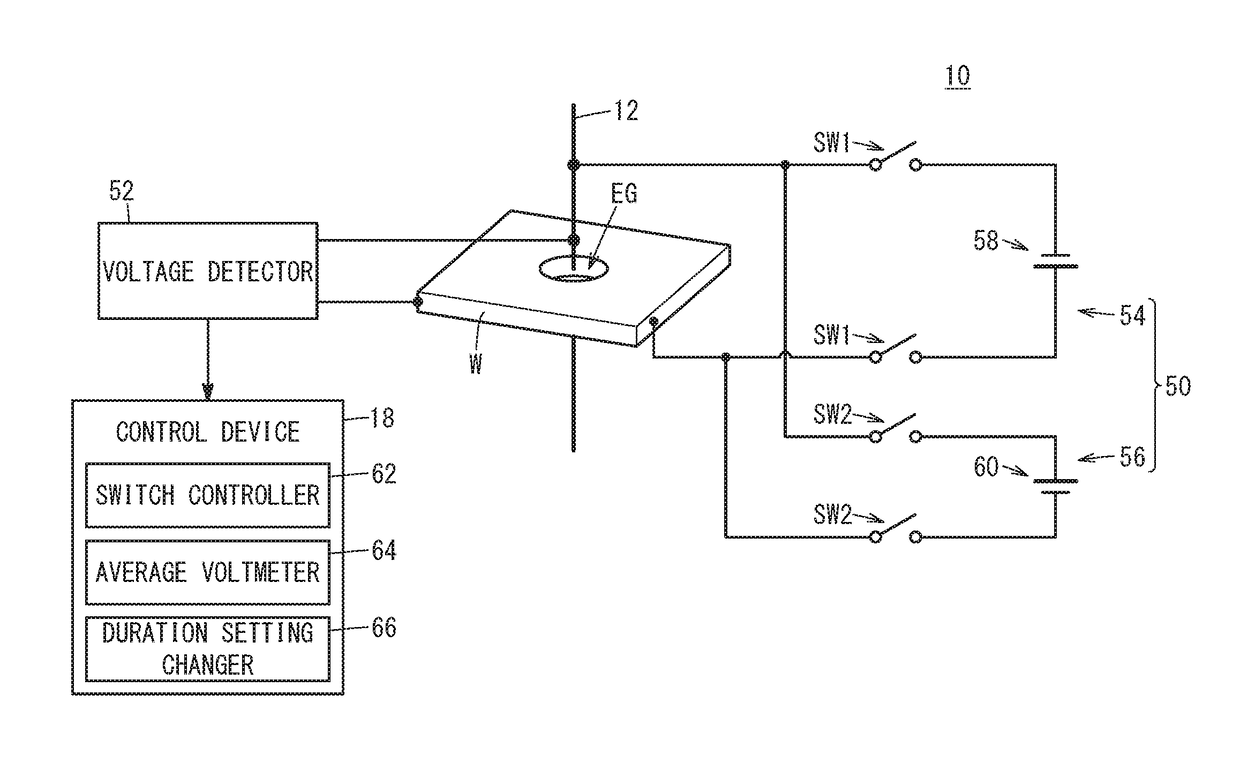
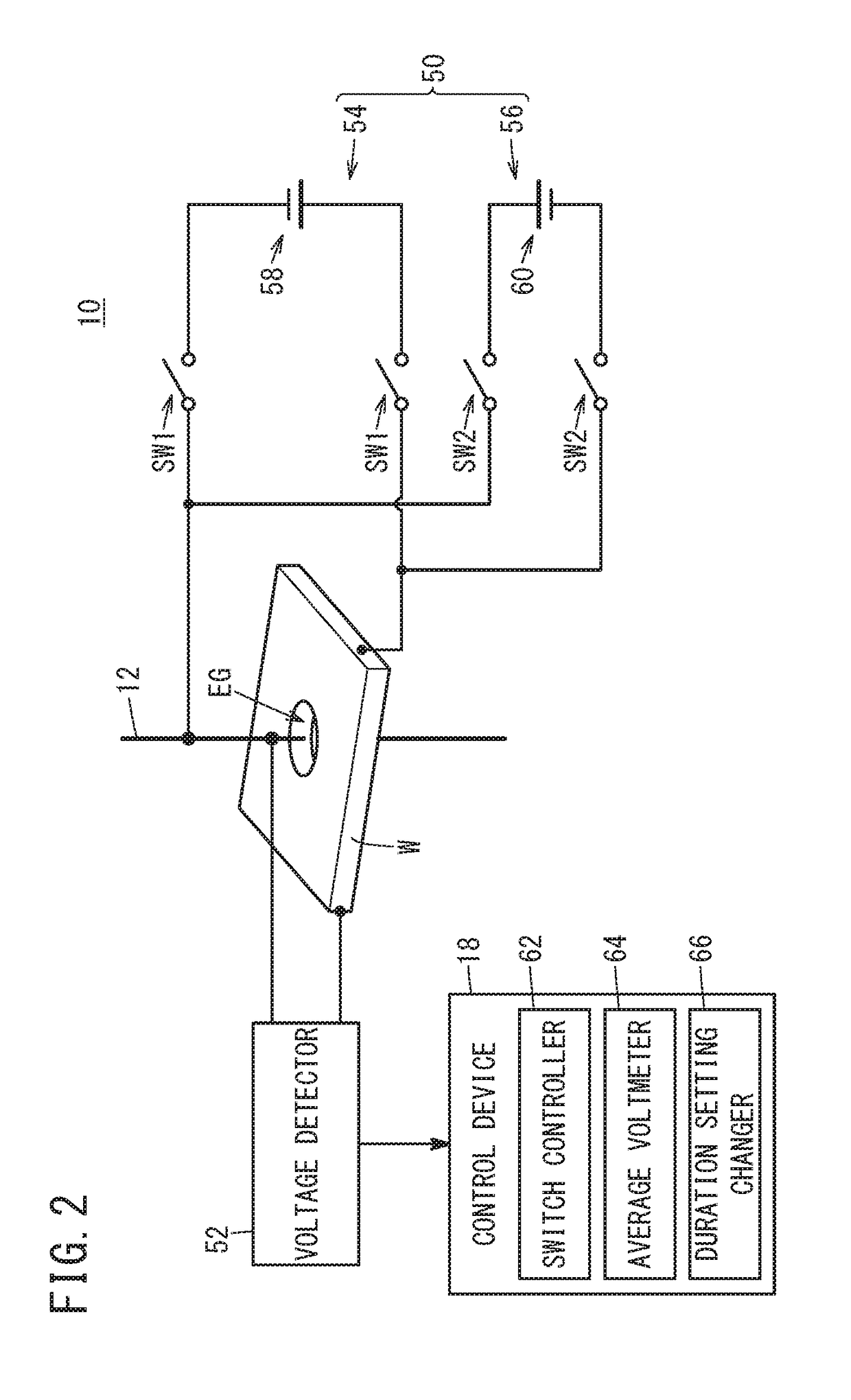
[0086]FIG. 9 is an electrical circuit configuration diagram of the wire electrical discharge machine 10 in a variational example 1. The same components as those in the above embodiment are allotted with the same reference numerals, and only different components will be described.

[0087]In the variational example 1, the second voltage applying circuit 56 for applying reverse polarity voltage to the electrode gap EG further includes current limiting resistors R2 inserted between the second DC power source 60 and the electrode gap EG. Specifically, each of the current limiting resistors R2 is inserted between the second switch SW2 and the electrode gap EG. That is, one current limiting resistor R2 is inserted between the second switch SW2 connected to the positive electrode of the second DC power source 60 and the wire electrode 12, and the other between the second switch SW2 connected to the negative electrode of the second DC power source 60 and the workpiece W.

[0...

##al example 2

Variational Example 2

[0091]FIG. 10 is an electrical circuit configuration diagram of the wire electrical discharge machine 10 in a variational example 2. The same components as those in the above embodiment are allotted with the same reference numerals, and only different components will be described.

[0092]In the variational example 2, the first voltage applying circuit 54 that applies positive voltage across the electrode gap EG further includes a first capacitor C1 connected in parallel with the first DC power source 58. The second voltage applying circuit 56 that applies reverse polarity voltage across the electrode gap EG further includes a second capacitor C2 connected in parallel with the second DC power source 60. Specifically, the first capacitor C1 is provided between the first switches SW1 and the first DC power source 58, and the second capacitor C2 is provided between the second switches SW2 and the second DC power source 60. Since the first switches SW1 and the first DC...


PUM

PropertyMeasurementUnit
Timeaaaaaaaaaa
Polarityaaaaaaaaaa
Electric potential / voltageaaaaaaaaaa

Abstract

A wire electrical discharge machine includes a first voltage applying circuit, a second voltage applying circuit, and a switch controller. The first voltage applying circuit includes a first DC power source for applying a positive polarity voltage across an electrode gap, and a first switch for on/off-switching of application of the positive polarity voltage. The second voltage applying circuit includes a second DC power source for applying a reverse polarity voltage to the electrode gap, and a second switch for on/off-switching of application of the reverse polarity voltage. The switch controller controls the first switch and the second switch so that the first switch and the second switch are not turned on simultaneously. The first DC power source and the second DC power source are set up so that the absolute value of the reverse polarity voltage is lower than the absolute value of the positive polarity voltage.

Description

CROSS-REFERENCE TO RELATED APPLICATION[0001]This application is based upon and claims the benefit of priority from Japanese Patent Application No. 2016-170605 filed on Sep. 1, 2016, the contents of which are incorporated herein by reference.BACKGROUND OF THE INVENTIONField of the Invention[0002]The present invention relates to a wire electrical discharge machine for machining a workpiece with a wire electrode.Description of the Related Art[0003]In the wire electrical discharge machine, not only the object to be processed but also the wire electrode itself wears and diminishes. When a workpiece is machined in a (dielectric) working fluid, in order to prevent occurrence of electric corrosion or adhesion of a coating to the workpiece due to electrolytic action, it is a common practice to perform electrical discharge machining by applying AC voltage between the wire electrode and the workpiece (across the electrode gap).[0004]When voltage (a positive polarity voltage), with the workpiec...

Claims


Application Information

Patent Timeline
IPC IPC(8): B23H7/30B23H1/02B23H7/20B23H7/10B23H1/04B23H7/06
CPCB23H7/30B23H1/024B23H7/20B23H1/028B23H1/04B23H7/065B23H7/10B23H7/04B23H7/105B23H2300/20B23H1/022B23H7/14B23H1/02B23H2600/10
Inventor FURUTA, TOMOYUKIMATSUNAGA, TOMOAKI
Owner FANUC CORP
Why Eureka
Try Eureka