Rotary mold type injection molding machine and method for exchanging mold of rotary mold type injection molding machine

a rotary mold type and injection molding machine technology, which is applied in the field of rotary mold type injection molding machine and method for exchanging molds of rotary mold type injection molding machines, can solve the problems of not revealing at all how to mount molds, requiring time and skill to exchange a plurality of molds by using cranes, and mold mounting plates or the like cannot be completely mounted on one of the plates, so as to achieve the effect of easy mold exchanging in a short tim

Active Publication Date: 2018-03-01
JAPAN STEEL WORKS LTD
View PDF24 Cites 4 Cited by
  • Summary
  • Abstract
  • Description
  • Claims
  • Application Information

AI Technical Summary

Benefits of technology

[0006]However, JP 7-321 B (Claim 1, Advantageous Effect of Invention, FIGS. 1 and 2) relates to a vertical rotary type injection molding machine in which a movable platen is lifted and lowered with respect to a lower fixed platen, and the mold mounting plate can be horizontally moved and carried onto the lower fixed platen. Accordingly, movement and attachment and detachment of the mold mounting plate can be carried out under minimal influence of gravity. In contrast, in a case of a horizontal rotary mold type molding machine, even if a mold is carried in and mounted in a state where the mold mounting plate is attached to the mold, the mold mounting plate or the like cannot be mounted completely on one of the platens and the mold mounting plate is always affected by gravity. Therefore, it is difficult to maintain posture of the mold mounting plate until the mold mounting plate has been carried in or mounted. Therefore, JP 7-321 B (Claim 1, Advantageous Effect of Invention, FIGS. 1 and 2) cannot be diverted immediately to a method for exchanging molds of a horizontal rotary mold type injection molding machine. Also, attachment work of temperature control liquid piping or the like after a mold is mounted in the vertical rotary mold type molding machine as disclosed in JP 7-321 B (Claim 1, Advantageous Effect of Invention, FIGS. 1 and 2) totally differs from the attachment work in a horizontal rotary mold type molding machine. Therefore, in this respect as well, it is impossible to immediately divert JP 7-321 B (Claim 1, Advantageous Effect of Invention, FIGS. 1 and 2) to a method for exchanging molds of a horizontal rotary mold type injection molding machine.
[0007]Accordingly, in view of the above problems, an object of the present invention is to provide a rotary mold type injection molding machine including a fixed platen, a movable platen which is opened and closed in a horizontal direction with respect to the fixed platen, and a rotary table to which a plurality of molds is mounted and which is rotatably provided on one of the fixed platen and the movable platen, the rotary mold type injection molding machine being capable of relatively easily exchanging molds in a short time, and to provide a method for exchanging molds of the rotary mold type injection molding machine.
[0008]A first aspect of the present invention provides a rotary mold type injection molding machine including: a fixed platen; a movable platen which is opened and closed in a horizontal direction with respect to the fixed platen; and a rotary table to which a plurality of molds is mounted and which is rotatably provided on one of the fixed platen and the movable platen, the rotary mold type injection molding machine further including: a mold member which is configured of a plurality of molds and a mold mounting plate to which the plurality of molds is mounted; and a mounting portion which is provided on the rotary table of the fixed platen or movable platen and on which the mold mounting plate is mounted when the mold member is fixed.
[0009]A second aspect of the present invention provides the rotary mold type injection molding machine according to the first aspect, wherein the mounting portion is a mold-member moving mechanism which moves the mold member in the horizontal direction, and carrying-in or carrying-out of the mold member is performed from between upper and lower tie bars on at least one of an operation side or a side opposite to the operation side.
[0010]A third aspect of the present invention provides a method for exchanging molds of a rotary mold type injection molding machine including: a fixed platen; a movable platen which is opened and closed in a horizontal direction with respect to the fixed platen; and a rotary table to which a plurality of molds is mounted and which is rotatably provided on one of the fixed platen and the movable platen, the rotary mold type injection molding machine further including a mold member which is configured of a plurality of molds that are mounted on a mold mounting plate on a rotary table side and on a mold mounting plate on a side opposite to the rotary table side, the method including positioning and fixing the mold member on the rotary table in a state where at least the mold mounting plate on the rotary table side in the mold member is mounted on a mounting portion of the rotary table.
[0011]A fourth aspect of the present invention provides the method for exchanging molds of a rotary mold type injection molding machine according to the third aspect, further including carrying in and fixing the mold member to the rotary table in a state where two rotary molds are aligned in a vertical direction of the mold mounting plate on the rotary table side.

Problems solved by technology

However, JP 2007-276261 A (Claim 1, 0003, 0018, FIG. 1) does not disclose at all how to mount the mold on the mold mounting plate.
As a result, it requires time and skill to exchange a plurality of molds by using a crane.
In contrast, in a case of a horizontal rotary mold type molding machine, even if a mold is carried in and mounted in a state where the mold mounting plate is attached to the mold, the mold mounting plate or the like cannot be mounted completely on one of the platens and the mold mounting plate is always affected by gravity.
Therefore, it is difficult to maintain posture of the mold mounting plate until the mold mounting plate has been carried in or mounted.

Method used


Image

  • Rotary mold type injection molding machine and method for exchanging mold of rotary mold type injection molding machine
  • Rotary mold type injection molding machine and method for exchanging mold of rotary mold type injection molding machine
  • Rotary mold type injection molding machine and method for exchanging mold of rotary mold type injection molding machine

Examples


Embodiment Construction

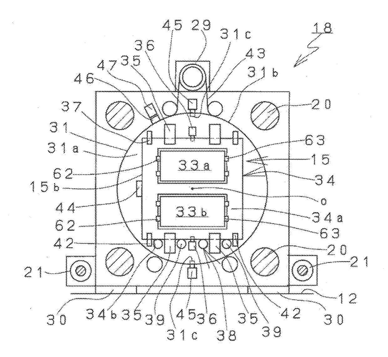
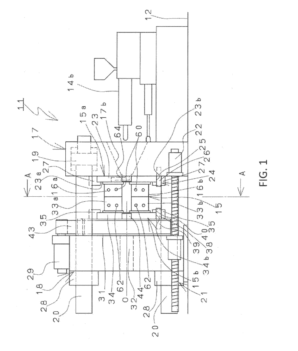
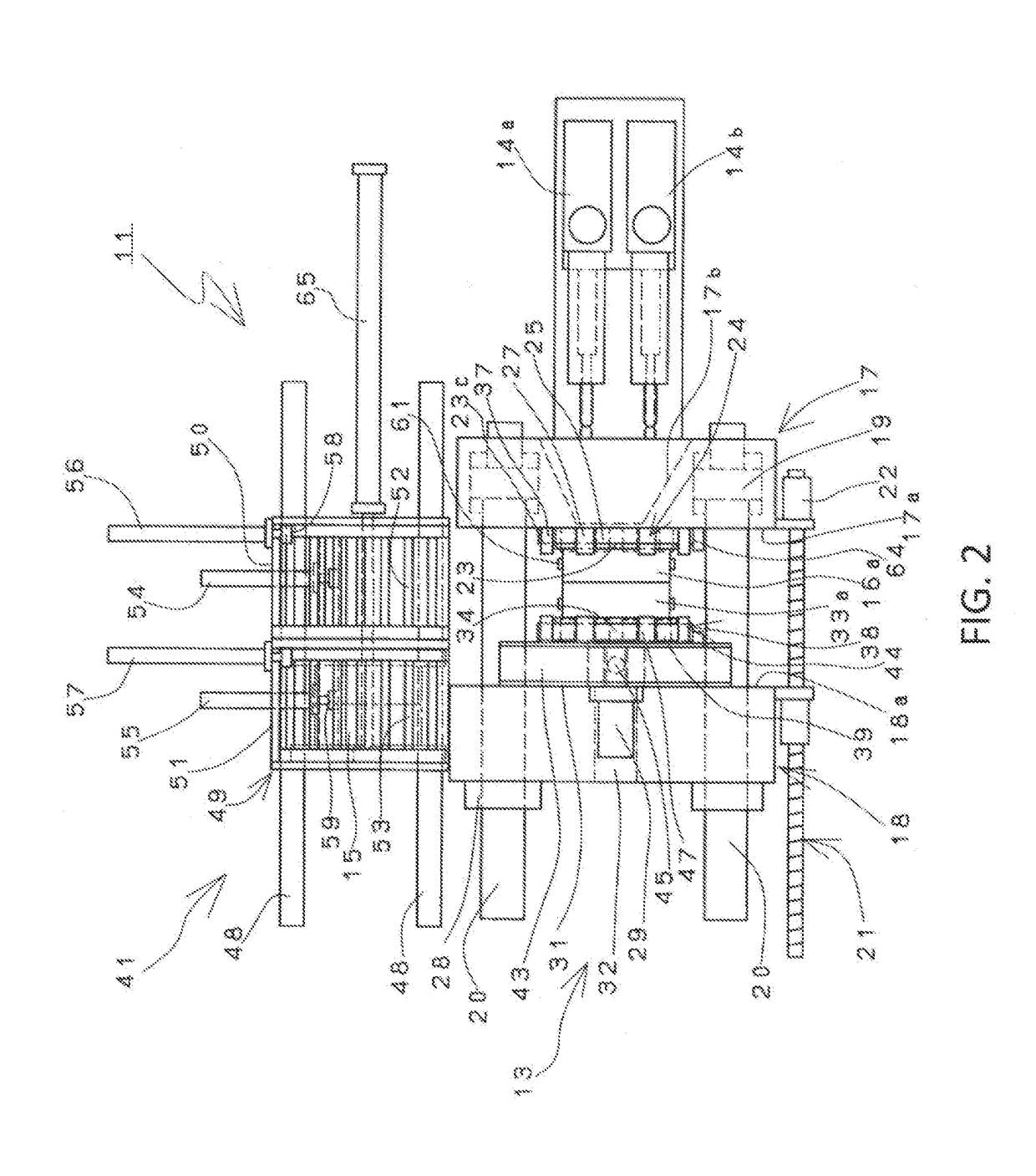
[0017]An outline of a rotary mold type injection molding machine according to an embodiment of the present invention will be described with reference to FIGS. 1 to 3. A rotary mold type injection molding machine 11 according to the present invention is basically configured of a mold clamping device 13 provided on one side in the longitudinal direction on a base 12, and injection devices 14a, 14b provided on the other side in the longitudinal direction on the base 12. The rotary mold type injection molding machine 11 includes a fixed platen which is fixedly provided on the base 12 of the mold clamping device 13, a movable platen 18 which is opened and closed in the horizontal direction with respect to the fixed platen, and a rotary table 31 to which a plurality of molds 33a and 33b is mounted and which is rotatably provided on one of the fixed platen 17 and the movable platen 18.

[0018]Next, the mold member 15 of the rotary mold type injection molding machine 11 will be described. In ...


PUM

PropertyMeasurementUnit
distanceaaaaaaaaaa
sizeaaaaaaaaaa
timeaaaaaaaaaa

Abstract

A rotary mold type injection molding machine and a method for exchanging molds of a rotary mold type injection molding machine. The rotary mold type injection molding machine includes a fixed platen, a movable platen which is opened and closed in a horizontal direction with respect to the fixed platen, and a rotary table to which a plurality of molds is mounted and which is rotatably provided on one of the fixed platen and the movable platen. The rotary mold type injection molding machine further includes: a mold member which is configured of a plurality of molds and mold mounting plates to which the plurality of molds is mounted; and a mounting portion which is provided on the rotary table provided on one of the fixed platen and the movable platen and on which the mold mounting plate is mounted when the mold member is fixed.

Description

CROSS REFERENCE TO RELATED APPLICATIONS[0001]This application claims the priority benefit of Japanese Patent Application No. 2016-162421, filed on Aug. 23, 2016. The entirety of the above-mentioned patent application is hereby incorporated by reference herein and made a part of this specification.BACKGROUND1. Technical Field[0002]The present invention relates to a rotary mold type injection molding machine including a fixed platen, a movable platen which is opened and closed in a horizontal direction with respect to the fixed platen, and a rotary table to which a plurality of molds is mounted and which is rotatably provided on one of the fixed platen and the movable platen, and a method for exchanging molds of a rotary mold type injection molding machine.2. Related Art[0003]JP 2007-276261 A (Claim 1, 0003, 0018, FIG. 1) discloses a known rotary mold type injection molding machine (horizontal rotary mold type injection molding machine) in which a movable platen is opened and closed i...

Claims


Application Information

Patent Timeline
Patent Type & Authority Applications(United States)
IPC IPC(8): B29C45/04
CPCB29C45/045B29C45/062B29C45/1756B29C45/162B29C45/06
Inventor FUKUMOTO, KENJIMIYAKI, TSUYOSHIJINNO, SHIZUO
Owner JAPAN STEEL WORKS LTD
Why Eureka
Try Eureka