
A Steering Column Assembly

a technology of steering column and assembly, which is applied in the direction of shock absorption, elastic dampers, transportation and packaging, etc., can solve the problem of difficult adjustment of steering column reach, and achieve the effect of reducing the number of fasteners

Active Publication Date: 2018-03-01
TRW LIMITED
View PDF9 Cites 8 Cited by
  • Summary
  • Abstract
  • Description
  • Claims
  • Application Information

AI Technical Summary

Benefits of technology

The invention describes a steering column assembly that has a laminated strap design that allows for easy interchange of different straps without changing their energy absorption characteristics. The laminated strap is secured to the first bracket using a common fastener, which reduces the number of fasteners needed. The laminated strap has multiple strips that can be adjusted to tune its energy absorption characteristics. The strips may also have cutouts to tailor resistance to collapse forces as the strap unwinds. Overall, the invention provides a flexible and customizable steering column assembly that can easily adjust to different vehicle crash requirements.

Problems solved by technology

For a steering column assembly that is adjustable for reach the normal range of adjustment will correspond to the allowable reach adjustment of the steering and this should not be opposed by the energy absorbing device, since that would make the steering difficult to adjust for reach.

Method used


Image

  • A Steering Column Assembly
  • A Steering Column Assembly
  • A Steering Column Assembly

Examples


Embodiment Construction

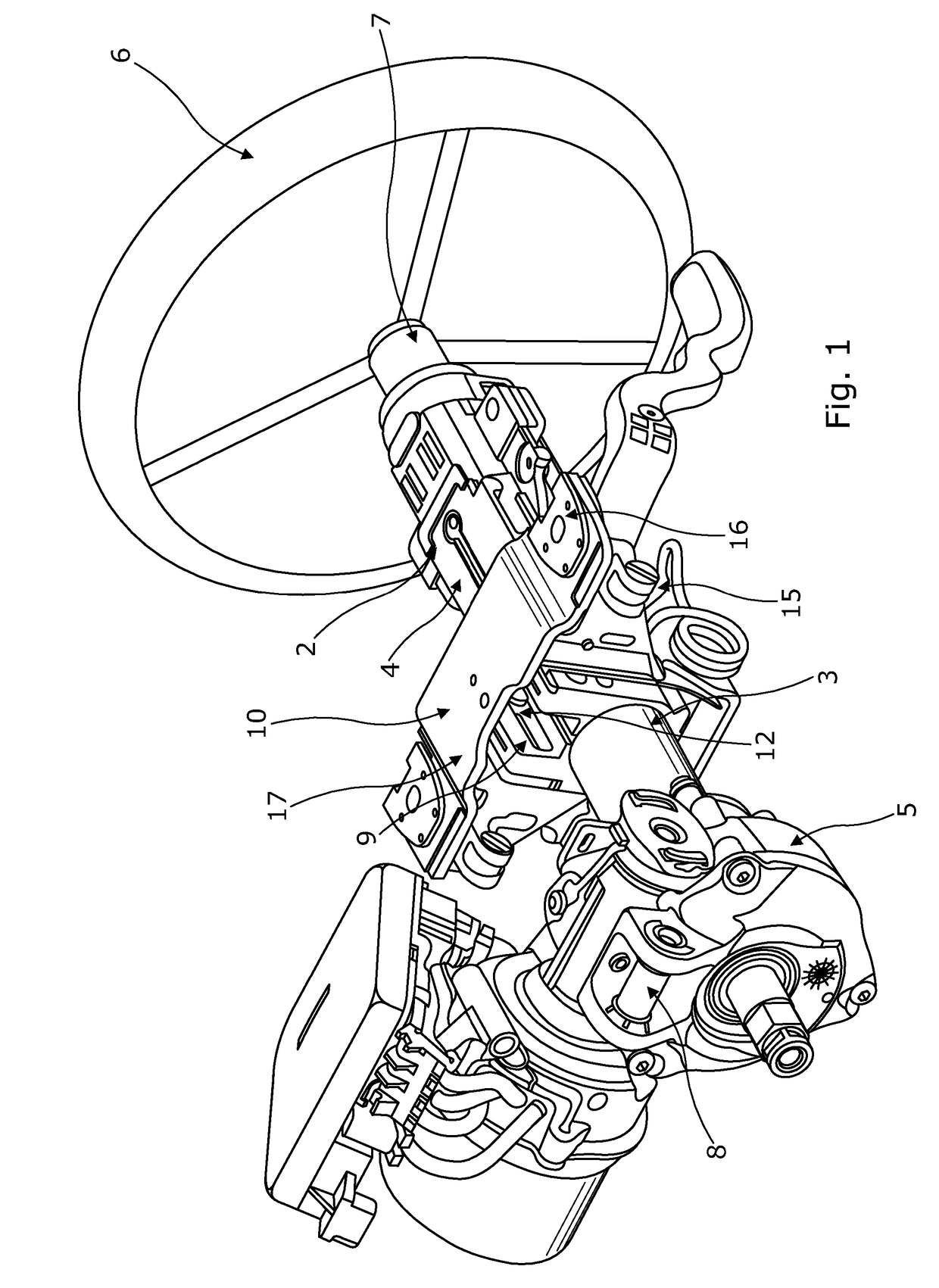
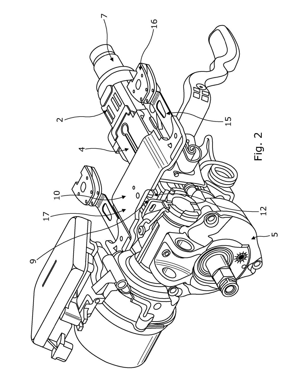
[0059]As shown in FIG. 1 a steering column assembly 1 comprises a telescopic steering column shroud 2 comprising an inner member 3 and an outer member 4 which receives a portion of the inner member. The inner and outer members 3, 4 are metal tubes with the inside diameter of the outer member 4 being only slightly greater than the outside diameter of the inner member 3 so as to permit relative movement between them by sliding. In the example of FIG. 1 the inner member 3 is attached to gearbox housing 5 whilst the outer member 4 extends away from that towards a steering wheel 6. This housing 5 may contain a gearbox in the case of an electric power steering system which is driven by an electric motor to provide an assistance torque. This tube in tube combination can also be reversed so the large tube is adjacent to the housing 5.

[0060]The steering wheel 6 is supported by a telescopic steering shaft 7 that is free to rotate within the steering column shroud 2. An example could be a bush...


PUM


Abstract

A steering column assembly comprises a first support bracket, a second support bracket, a shroud, and an energy absorbing device. The energy absorbing device comprises a laminated strap having discrete first and second layers, each formed from a separate elongate strip of material that is free to slide over the other strip along a major portion of its length, a portion of the laminated strap being coiled into a spiral, a free end portion of the laminated strap passing through passing through an opening in the second support bracket or the shroud, the free end of a first one of the strips having an opening through which a fastener passes that secures the laminated strap to the first support bracket, and the free end of a second one of the straps being connected to the first strip in a region distal from the free end of the first strip.

Description

CROSS-REFERENCE TO RELATED APPLICATIONS[0001]This application is a national stage of International Application No. PCT / GB2016 / 050602, filed 7 Mar. 2016, the disclosures of which are incorporated herein by reference in entirety, and which claimed priority to Great Britain Patent Application No. 1504034.8, filed 10 Mar. 2015, the disclosures of which are incorporated herein by reference in entirety.BACKGROUND OF THE INVENTION[0002]This invention relates to improvements in steering column assemblies of the kind including a support bracket that permits collapse during a crash. It also relates to steering assemblies including a support bracket.[0003]Steering column assemblies for automotive vehicles and the like are increasingly required to be adjustable for steering wheel distance known as reach. This requires the column shroud, within which the steering column shaft attached to the steering wheel is rotatably located, to be fixed to the vehicle by a clamp mechanism which can be locked ...

Claims


Application Information

Patent Timeline
Patent Type & Authority Applications(United States)
IPC IPC(8): B62D1/19F16F7/12
CPCB62D1/195F16F7/123
Inventor KINGSTON-JONES, HARRYDAVIES, NICLAS
Owner TRW LIMITED
Learn More