
Reclosable airtight container and method of manufacture

Active Publication Date: 2018-03-01
GLOBAL PACKAGING SOLUTIONS
View PDF2 Cites 2 Cited by
  • Summary
  • Abstract
  • Description
  • Claims
  • Application Information

AI Technical Summary

Benefits of technology

The present invention provides fastener strips and sliders for reclosable containers that overcome previous limitations. The fastener strips have a sealing member with multiple sealing parts that engage with complementary sealing parts on another fastener strip. One of the sealing parts has a finger that improves sealing when the fastener strips are only partly engaged. The slider has a body with flanges or rails on its sides, and it is inserted into the container. The technical effects of this invention are better sealing and easier use of reclosable containers.

Problems solved by technology

A problem in the manufacture of slide fasteners for profile strips is to secure the slider to the profile strip, and to allow sealing of the fastener strip in an essentially leak-proof manner and to prevent removal of the sliders from the bag.

Method used


Image

  • Reclosable airtight container and method of manufacture
  • Reclosable airtight container and method of manufacture
  • Reclosable airtight container and method of manufacture

Examples


Embodiment Construction

[0022]The foregoing description and drawings merely explain and illustrate the invention and the invention is not limited thereto, except in so far as those who have the disclosures before them are able to make modifications and variations therein without departing from the scope of the invention.

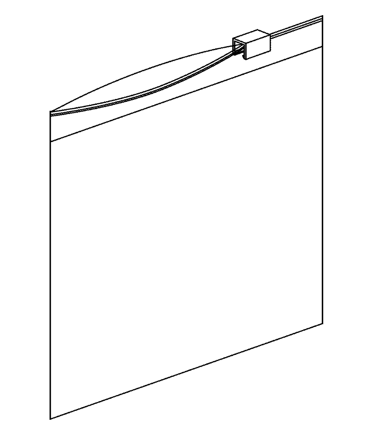
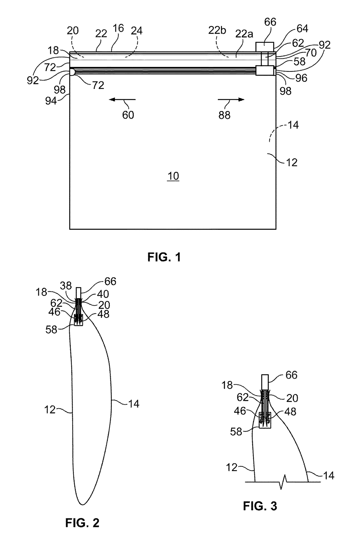
[0023]As shown in FIG. 1 of the drawings, a reclosable bag 10 having first and second walls 12 and 14 and an open top 16 is defined by first and second elongate flexible strips 18 and 20 attached to the first and second walls 12 and 14 respectively adjacent to the tops 22 and 24 of the walls 12 and 14. As best seen in FIGS. 2 and 4, one of the fastener strips 18 has a profile portion 26 forming at least one groove 28. The other fastener strip 20 has a profile portion 30 forming a rib 32 with a portion of the rib 34 received and retained within the groove 28 when the bag 10 is closed. Each of the strips 18 and 20 has a base 38 and 40 respectively connected to the respective walls 12 and 14, ...


PUM

PropertyMeasurementUnit
Flexibilityaaaaaaaaaa
Widthaaaaaaaaaa
Homogeneityaaaaaaaaaa

Abstract

The present invention includes a reclosable bag having first and second walls and an open top defined by first and second elongate flexible fastener strips attached to the first and second walls, respectively, adjacent the top of the walls. One of the fastener strips has a profile portion forming at least one groove and the other fastener strip has a profile portion forming at least one rib with a portion of each rib received and retained in one of said grooves when the bag top is closed. Each of the fastener strips has a base connected to the respective wall, and each of the strips has an upper edge adjacent the upper edge of the other strip. Third and fourth fastener strips are located within the bag walls parallel to and below the first and second fastener strips. The third and fourth fattener strips have one or more pairs of ribs and grooves. An inverted slider is mounted on the second and third fastener strips within the bag and is movable in one direction longitudinally of the third and fourth fastener strips to progressively separate the one or more rib from the one or more grooves to open the bag: the slider is also being movable in the opposite direction to progressively return the one or more rib portion to a retained condition in the one or more groove to close the bag. A plow extends from the slider to the exterior of said bag above the top of said bag. The plow has a finger tab extending affixed thereto at the distal end thereof. The plow is constructed and arranged to selectively separate said first and second rib and groove and to move said slider within said bag to separate said third and fourth rib and groove when said plow is moved longitudinally along said fastener strips from a first end of said strips to a second end of said strips. The plow is also constructed and arranged to slide said slider longitudinally along the third and fourth fastener strips from said second end and back to said first end so as to interlock said third and fourth ribs and groves and seal said third and fourth fastener strips within said bag. Alternatively, the Claim 1 first and second fastener strips may be selectively sealed by pressing the outer walls of said bag together proximate said first and second fastener strips so as to longitudinally interlock said first and second fastener strips together.

Description

BACKGROUND OF THE INVENTION[0001]The present invention relates generally to improvements in flexible fasteners of the type having releasably interlocking rib and groove elements with a slider to interlock or separate the rib and groove elements. The invention relates specifically to slide fasteners formed within the reclosable bag. The slide fasteners have two pairs of fastener strips running near the top of the bag and sealed to or integrally formed in the bag wall. Two of the fastener strips has an arrowhead shaped profile extending perpendicularly from and transverse to the top of the bag. The other oppositely opposed fastener strips has a C-shaped profile sized, constructed and arranged for the arrowhead shaped profiles.[0002]A problem in the manufacture of slide fasteners for profile strips is to secure the slider to the profile strip, and to allow sealing of the fastener strip in an essentially leak-proof manner and to prevent removal of the sliders from the bag.[0003]Accordin...

Claims


Application Information

Patent Timeline
IPC IPC(8): B65D33/25A44B19/16B65H45/00
CPCB65D33/2591B65H45/00A44B19/16B65D33/2541
Inventor BRANSON, MARK E.
Owner GLOBAL PACKAGING SOLUTIONS
Learn More