
Main heat exchanger and a process for cooling a tube side stream

a heat exchanger and side stream technology, which is applied in the direction of indirect heat exchangers, lighting and heating apparatus, stationary plate conduit assemblies, etc., can solve the problems of uneven temperature, and uneven heat transfer between the shell side and each of the first, second and third tube sides, etc., to achieve the effect of maximising the temperature of the evaporated refrigerant stream

Inactive Publication Date: 2018-03-01
LINDE AG
View PDF0 Cites 0 Cited by
  • Summary
  • Abstract
  • Description
  • Claims
  • Application Information

AI Technical Summary

Benefits of technology

This approach enhances the efficiency of the heat exchanger by ensuring uniform exit temperatures of tube side streams, matching tube side duty to shell side duty, even when the shell side is imbalanced, thus preventing efficiency drops and maintaining optimal operation.

Problems solved by technology

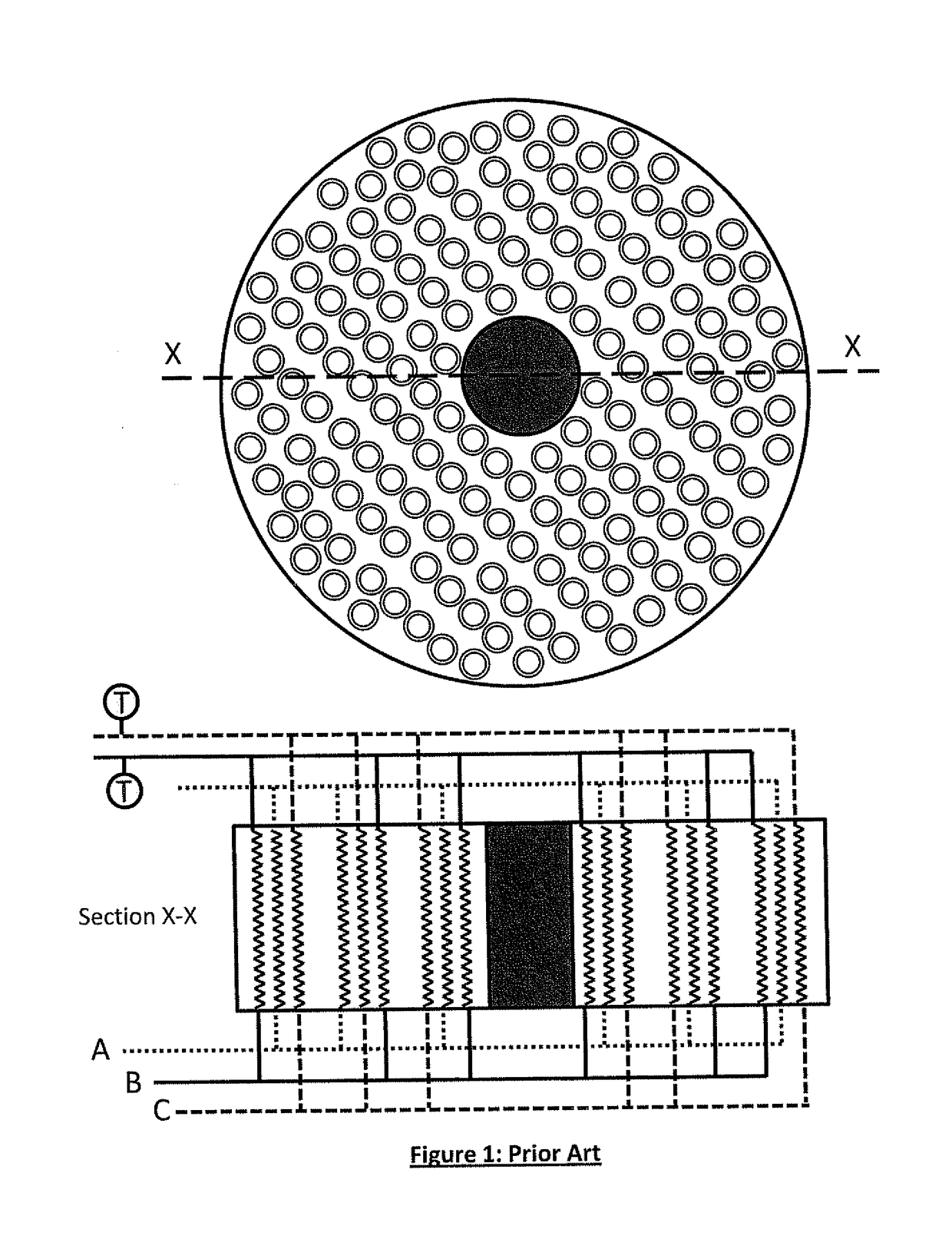
As spiral-wound heat exchangers become larger to perform increased duties, it becomes increasingly difficult to distribute the shell side fluids evenly.
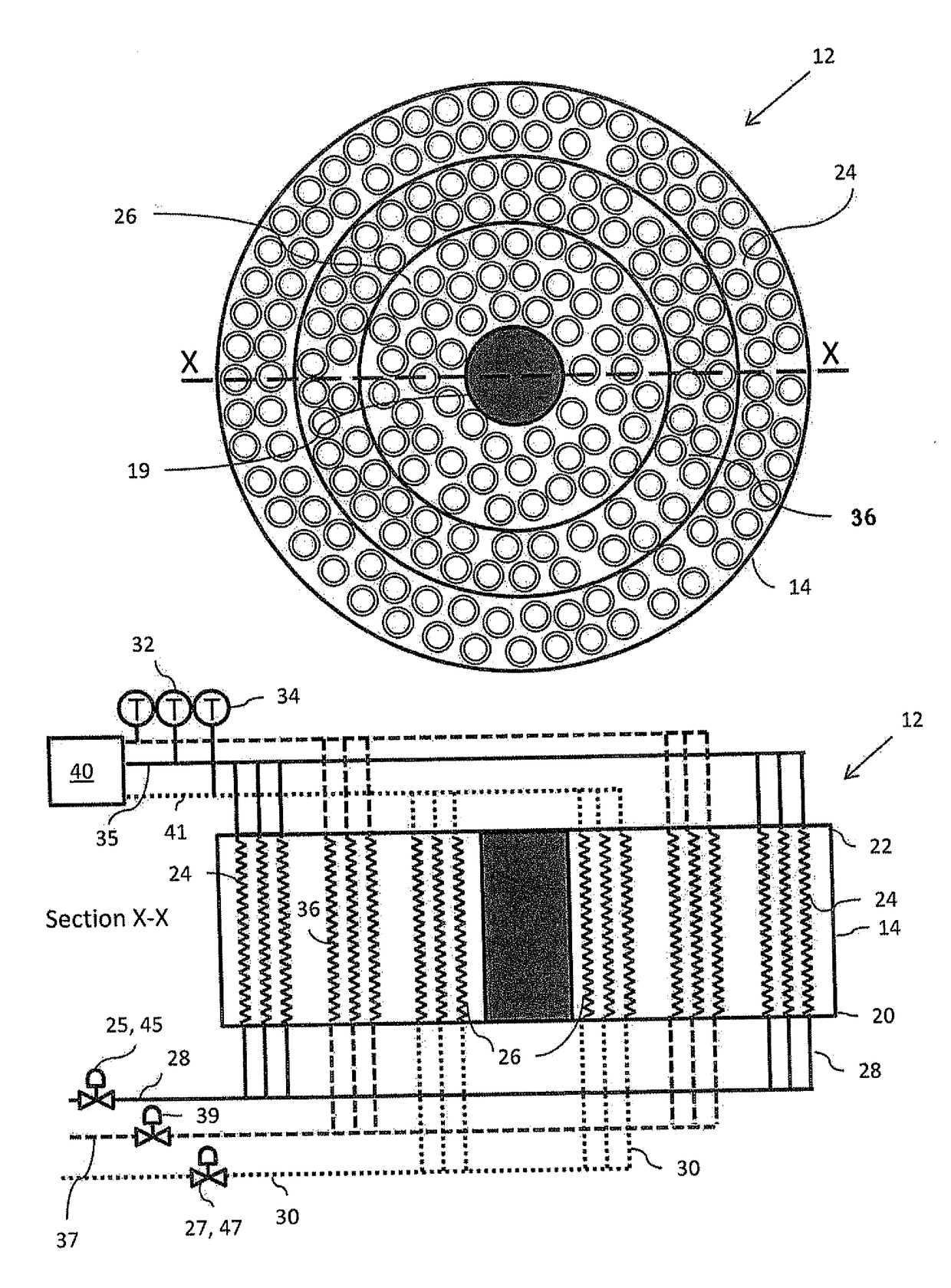
As a consequence, heat transfer between the shell side and each of the first, second and third tube sides may become uneven across the layers within the bundle.
This uneven distribution of temperature in the shell side fluids leads to unevenness in the temperature in portions of each of the tube side fluids at the cold ends of the bundle from each layer of tubes in the bundle, and for the shell-side fluid exiting at the warm end.
Such pinching causes a drop in efficiency of the main heat exchanger.
Any liquid present represents a significant loss of efficiency and must also be removed to avoid potential damage to the downstream refrigerant compression circuit.

Method used


Image

  • Main heat exchanger and a process for cooling a tube side stream
  • Main heat exchanger and a process for cooling a tube side stream
  • Main heat exchanger and a process for cooling a tube side stream

Examples


Embodiment Construction

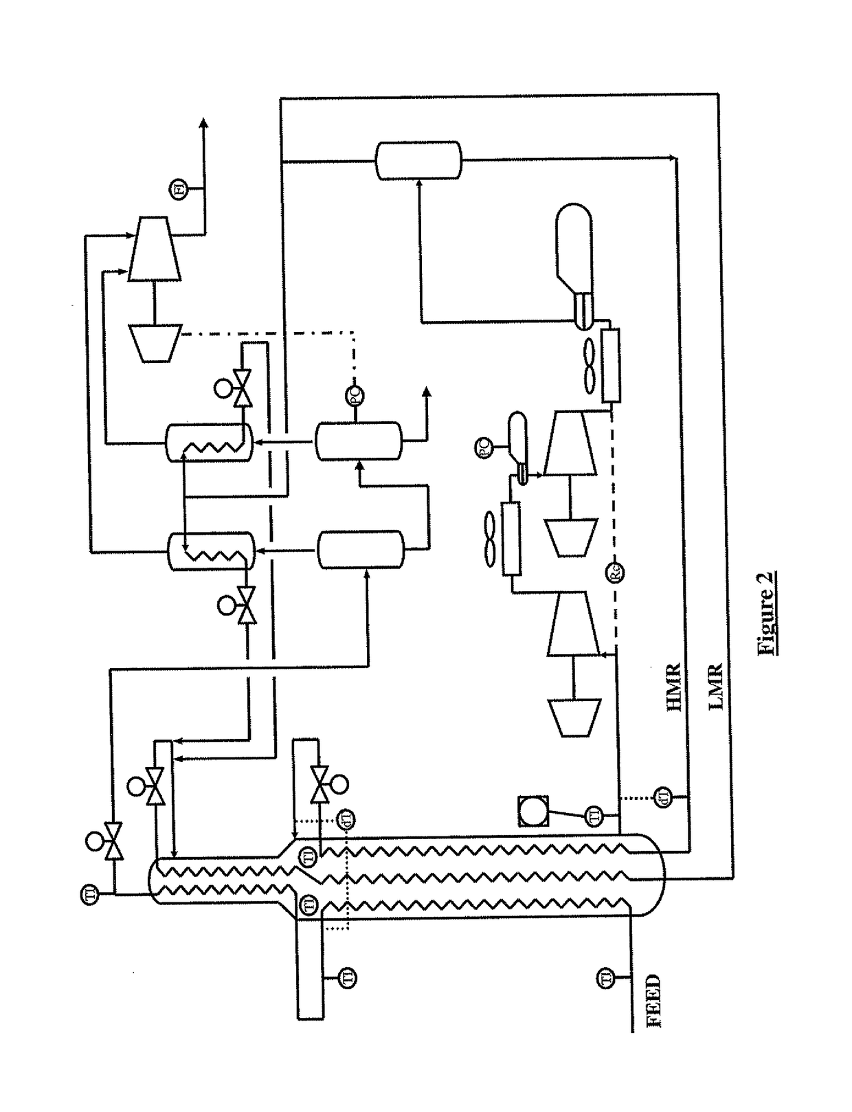
[0036]Particular embodiments of the process and apparatus of the present invention are now described, with particular reference to a plant for liquefying a gaseous, methane-rich feed gas in the form of natural gas in a main heat exchanger to produced liquefied natural gas, by way of example only.

[0037]The present invention is equally applicable to a main heat exchanger used for other applications such as the production of ethylene or other process requiring on two tube side streams instead of the three tube side streams described in detail below. The terminology used herein is for the purpose of describing particular embodiments only, and is not intended to limit the scope of the present invention. Unless defined otherwise, all technical and scientific terms used herein have the same meanings as commonly understood by one of ordinary skill in the art to which this invention belongs. In the drawings, it should be understood that like reference numbers refer to like parts.

[0038]Using ...


PUM


Abstract

A process for cooling a tube side stream in a main heat exchanger is described. The process comprises: a) supplying a first mass flow of a tube side stream to a first zone of individual tubes in the tube bundle; b) supplying a second mass flow of the tube side stream to a second zone of individual tubes in the tube bundle, the second zone being offset from the first zone; c) supplying a refrigerant stream on the shell side for cooling the first and second mass flows; d) removing the evaporated refrigerant stream from the warm end of the main heat exchanger; and, e) adjusting the first mass flow of the tube side stream relative to the second mass flow of the tube side stream to maximise the temperature of the removed evaporated refrigerant stream.

Description

FIELD OF THE INVENTION[0001]The present invention relates to a process for cooling a tube side stream in a main heat exchanger. The present invention further relates to a main heat exchanger for thermally processing a tube side stream. The present invention relates particularly though not exclusively to a process and a main heat exchanger for liquefying a gaseous, methane-rich feed to obtain a liquefied product known as “liquefied natural gas” or “LNG”.Background to the Invention[0002]A typical liquefaction process is described in U.S. Pat. No. 6,272,882 in which the gaseous, methane-rich feed is supplied at elevated pressure to a first tube side of a main heat exchanger at its warm end. The gaseous, methane-rich feed is cooled, liquefied and sub-cooled against evaporating refrigerant to get a liquefied stream. The liquefied stream is removed from the main heat exchanger at its cold end and passed to storage as liquefied product. Evaporated refrigerant is removed from the shell side...

Claims


Application Information

Patent Timeline
Patent Type & Authority Applications(United States)
IPC IPC(8): F28F9/00F25J5/00F28F27/02F28D7/02F28D7/00F25J1/02F25J1/00F24V30/00
CPCF25J2290/32F25J5/002F28F27/02F28D7/024F28D7/0066F28F9/001F25J1/0267F25J1/0262F25J1/0244F25J1/0055F25J1/0022F25J2220/62F25J2210/06F24V30/00F28D7/00F28D7/10F28D7/16F28D9/02
Inventor HO, SIEW-MUNG PATRICIAHODGES, DEREK WILLIAMKERBER, CHRISTIANESTEINBAUER, MANFREDHAMMERDINGER, MARKUS
Owner LINDE AG
Learn More