
Slim bezel backlight module and liquid crystal display apparatus having the same

a backlight module and slim bezel technology, applied in the field of slim bezel backlight module and liquid crystal display apparatus, can solve the problems of difficult processing and assembly of square-shaped adhesive tape for the slim bezel aspect, inability to firmly connect the square-shaped adhesive tape and the backlight module, etc., and achieve the effect of widening the display screen

Active Publication Date: 2018-03-01
WUHAN CHINA STAR OPTOELECTRONICS TECH CO LTD
View PDF1 Cites 1 Cited by
  • Summary
  • Abstract
  • Description
  • Claims
  • Application Information

AI Technical Summary

Benefits of technology

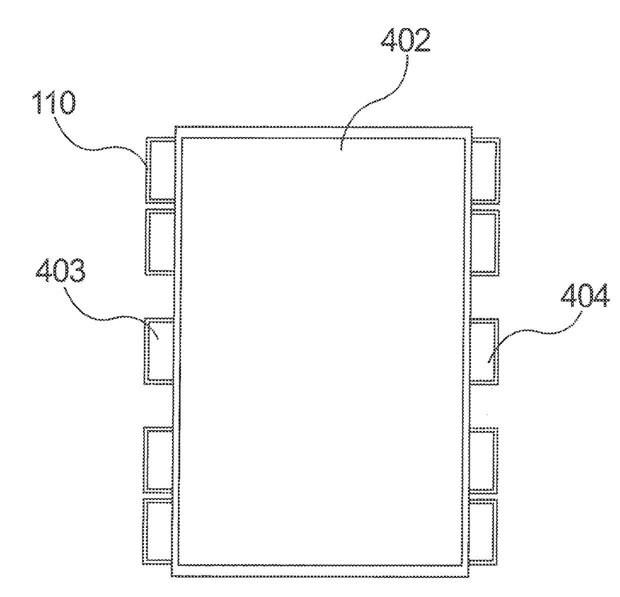
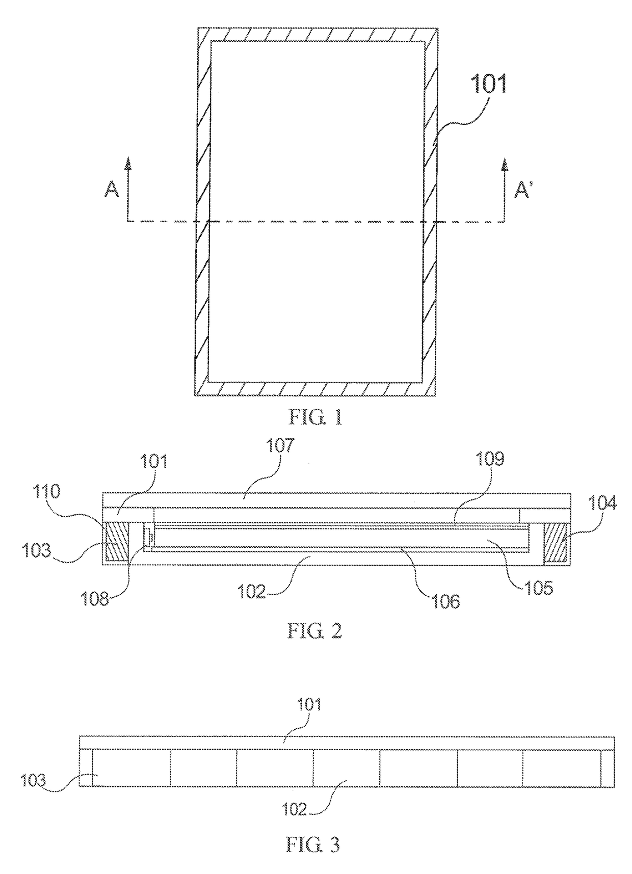
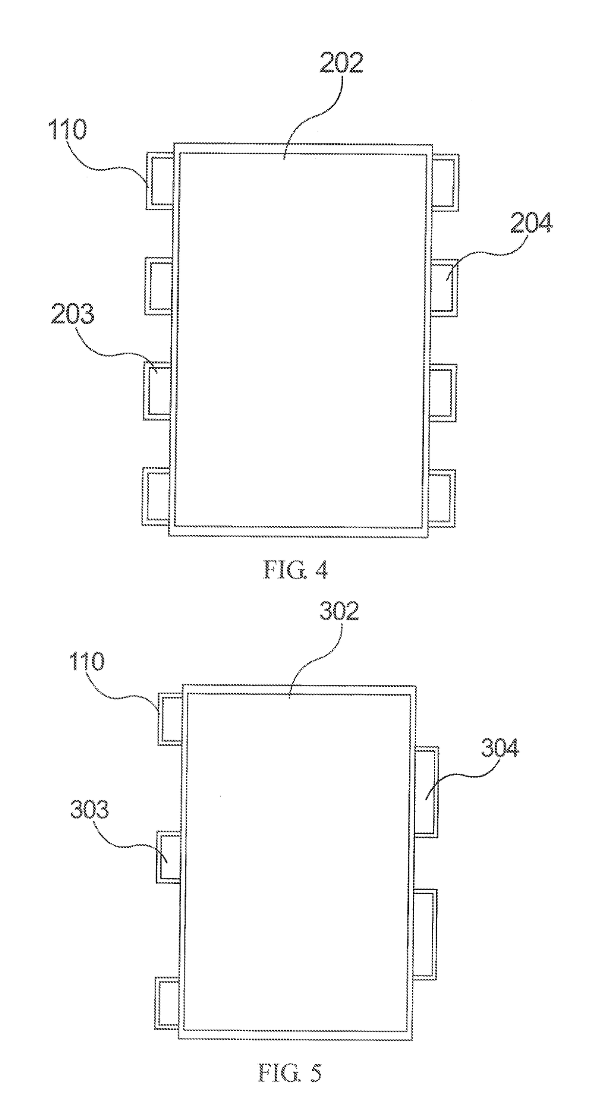
The present invention provides a slim bezel backlight module with a plastic frame that has better adhesion to the liquid crystal panel due to a wider adhesion area for the square-shaped adhesive tape. The plastic frame is integrated with iron material and plastic material, and a zigzagged surface is formed to increase the adhesion area. This solves the problem of lack of adequate border width and allows for a wider display screen compared to other liquid crystal display apparatuses of the same size. Overall, the slim bezel backlight module and the liquid crystal display apparatus have improved assembly and increased screen size.

Problems solved by technology

The border of current liquid crystal display modules has become slimmer, thereby resulting in a production limit of 0.45 mm for the border at two sides of the plastic frame.
Thus, the processing and assembling of the square-shaped adhesive tape for the aspect of slim bezel is quite difficult.
Therefore, a technical problem existing in the conventional technology is that when the border width of a conventional plastic frame structure is too small for a square-shaped adhesive tape to have sufficient adhesion area to be adhered thereon, a firmly-connection between the square-shaped adhesive tape and the backlight module cannot be achieved.

Method used


Image

  • Slim bezel backlight module and liquid crystal display apparatus having the same
  • Slim bezel backlight module and liquid crystal display apparatus having the same
  • Slim bezel backlight module and liquid crystal display apparatus having the same

Examples


Embodiment Construction

[0069]The foregoing objects, features and advantages adopted by the present invention can be best understood by referring to the following detailed description of the preferred embodiments and the accompanying drawings. Furthermore, the directional terms described in the present invention, such as upper, lower, front, rear, left, right, inner, outer, side and etc., are only directions referring to the accompanying drawings, so that the used directional terms are used to describe and understand the present invention, but the present invention is not limited thereto. In the drawings, similar structural units are designated by the same reference numerals.

[0070]To solve the technical problem in the assembly process of a conventional backlight module that the plastic bezel is too slim for a square-shaped adhesive tape to be fully adhered thereto, which causes the square-shaped adhesive tape to be unable to firmly connect the backlight module and a liquid crystal panel, the present provid...


PUM


Abstract

A slim bezel backlight module and a liquid crystal display apparatus having the same are disclosed. The backlight module includes a light source, a light guide plate, a reflector, a plastic frame assembly and a square-shaped adhesive tape. The plastic frame assembly is designed to be integrated by iron material and plastic material, and a few plastic portions of the plastic frame assembly protruded from the sides of the plastic frame assembly to form a zigzagged surface for increasing the adhesion area for the square-shaped adhesive tape, thereby solving the problem that the lack of enough border width makes the plastic frame assembly hard to be processed and assembled.

Description

BACKGROUND OF THE INVENTIONField of the Invention[0001]The present invention relates to the technical field of liquid crystal display, and more particularly to a slim bezel backlight module and a liquid crystal display apparatus having the slim bezel backlight module.Description of the Related Art[0002]With the development of mobile communication products and tablet computers, a lot of mobile phone manufacturers use “slim bezel” as a selling point to attract consumers. The width of a plastic frame of a backlight module is in direct relation to the border width of a mobile phone.[0003]In a traditional backlight module, a black-white double-faced or black-black double-faced square-shaped adhesive tape will be adhered to the plastic frame so as to achieve connecting the liquid crystal module and the backlight module and preventing separation of optical films. In the meantime, the square-shaped adhesive tape is further used to block the gaps between the light guide plate and the optical...

Claims


Application Information

Patent Timeline
IPC IPC(8): F21V8/00
CPCG02B6/0088G02B6/0055G02B6/0065G02F1/133308G02F1/133608G02F1/133314G02F1/133322
Inventor ZHANG, WEICHEN, SHIH HSIANG
Owner WUHAN CHINA STAR OPTOELECTRONICS TECH CO LTD
Learn More