Inner-Rotor Type Motor and Stator Thereof

Inactive Publication Date: 2018-03-01
SUNONWEALTH ELECTRIC MACHINE IND
View PDF4 Cites 2 Cited by
  • Summary
  • Abstract
  • Description
  • Claims
  • Application Information

AI Technical Summary

Benefits of technology

[0007]It is therefore the objective of this disclosure to provide an inner-rotor motor and a stator thereof. In the motor, the insulating sleeve of the stator is provided with at least one positioning member to which the enameled copper wi

Problems solved by technology

This leads to an abnormal operation of the inner-rotor motor.
Due to this reason, special care should be taken during the assembly of the motor, leading to a difficulty in improving the assembly efficiency.
However, this structure increases the coupling area between the housing and the s

Method used


Image

  • Inner-Rotor Type Motor and Stator Thereof
  • Inner-Rotor Type Motor and Stator Thereof
  • Inner-Rotor Type Motor and Stator Thereof

Examples


Example

[0027]In the various figures of the drawings, the same numerals designate the same or similar parts. Furthermore, when the terms “first”, “second”, “inner”, “outer”, “top” and similar terms are used hereinafter, it should be understood that these terms have reference only to the structure shown in the drawings as it would appear to a person viewing the drawings, and are utilized only to facilitate describing the disclosure.

DETAILED DESCRIPTION OF THE INVENTION

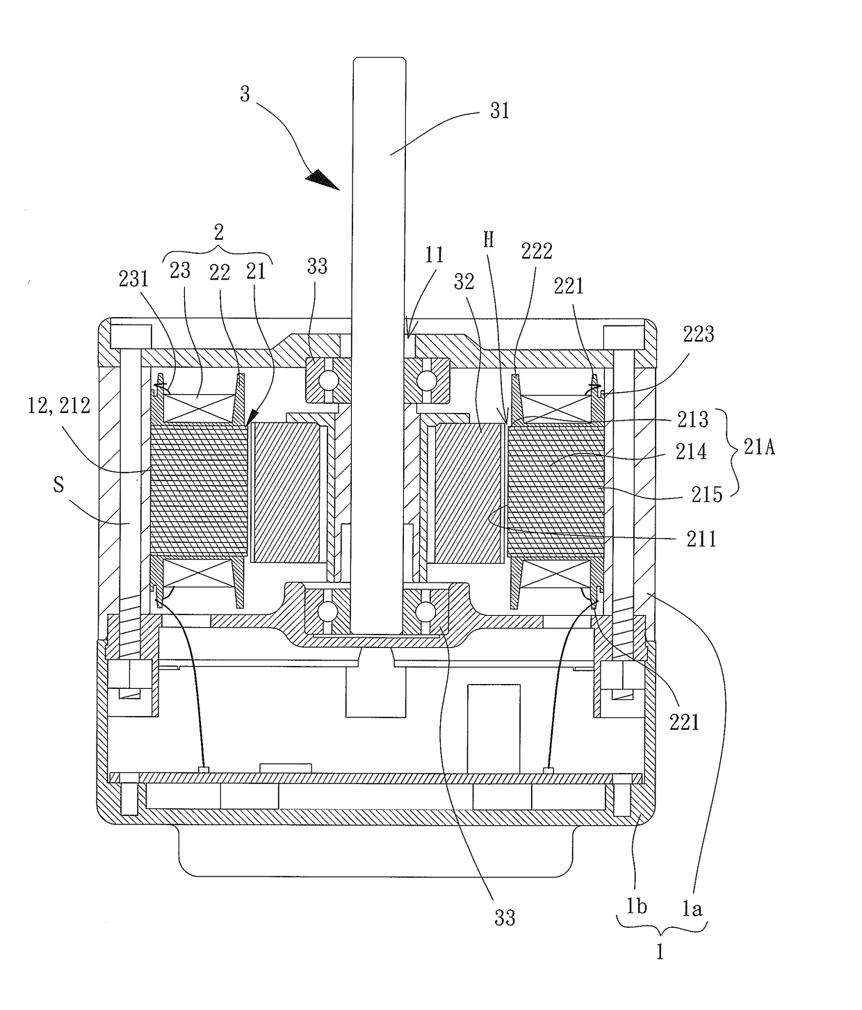
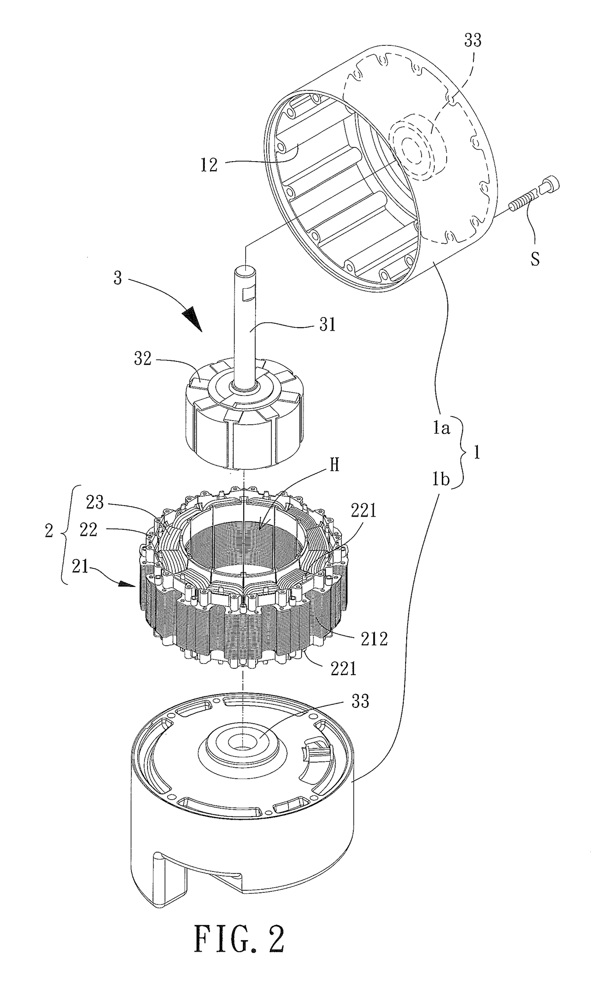
[0028]FIGS. 2 and 4 show an inner-rotor motor according to an embodiment of the disclosure. The motor generally includes a housing 1, a stator 2 and a rotor 3. The stator 2 is received in the housing 1. The rotor 3 is partially received in the housing 1.

[0029]In the embodiment, the housing 1 includes a first housing part 1a and a second housing part 1b. The stator 2 includes an iron core 21, an insulating sleeve 22 and a coil unit 23. The iron core 21, the insulating sleeve 22 and the coil unit 23 and a part of the rotor 3 are ...


PUM


Abstract

An inner-rotor motor including a housing, a stator and a rotor is provided to avoid the damage to the coil unit which often occurs during the assembly of the conventional inner-rotor motor. The housing has an inner periphery provided with a plurality of protrusions. The iron core has an outer periphery provided with a plurality of notches. The insulating sleeve includes a plurality of positioning members. In radial directions perpendicular to the shaft, each of the plurality of notches is spaced from a center of a shaft at a minimal distance, and each of the plurality of positioning members is spaced from the center of the shaft at a maximal distance. The maximal distance is smaller than the minimal distance.

Description

CROSS REFERENCE TO RELATED APPLICATIONS[0001]The application claims the benefit of Taiwan application serial No. 105128294, filed on Sep. 1, 2016, and the subject matter of which is incorporated herein by reference.BACKGROUND OF THE INVENTION1. Field of the Invention[0002]The present disclosure generally relates to a motor and, more particularly, to an inner-rotor motor and a stator thereof.2. Description of the Related Art[0003]An inner-rotor motor generally includes a housing, a stator and a rotor. The stator is mounted in the housing. The rotor is rotatably coupled with the housing via a shaft. The rotor includes a magnet portion mounted at the center of the stator for magnetic conduction purposes.[0004]FIG. 1 is a partial view of a conventional stator 9 of an inner-rotor motor. The conventional stator 9 includes an iron core 91, an insulating winding frame 92 and a coil unit 93. The insulating winding frame 92 includes a ring 921 connected to the top face of the iron core 91. A ...

Claims


Application Information

Patent Timeline
IPC IPC(8): H02K3/34H02K3/32
CPCH02K3/325H02K3/345H02K1/12H02K1/146
Inventor HORNG, ALEXYIN, TSO-KUOSHAN, DUO-NIAN
Owner SUNONWEALTH ELECTRIC MACHINE IND
Why Eureka
Try Eureka