Industrial hydroponic control apparatus

Inactive Publication Date: 2018-03-08
BILLINGS SCOTT
View PDF4 Cites 7 Cited by
  • Summary
  • Abstract
  • Description
  • Claims
  • Application Information

AI Technical Summary

Benefits of technology

[0006]The invention disclosed herein addresses the above-mentioned need for an apparatus, which monitors ambient condition levels for optimal growth of the plants and notifies users of a malfunction or reduction in ambient condition levels. Furthermore, the invention disclosed herein addresses a need for an apparatus, which supplies chilled nutrient-rich fluids to a plant. Moreover, the invention addresses a need for an apparatus, which is capable of dehumidifying the air surrounding the plant growing area. Additionally, the invention addresses a need for an apparatus that can interface with horticulture tracking software and records events in real time via the internet. The industrial hydroponic control apparatus for monitoring and modifying an environment for growing plants comprises a portable table, a reservoir, a refrigerator assembly, and a control device. The portable table comprises a plurality of predetermined positions for mounting a plur

Problems solved by technology

Additionally, these systems lack portability thereby reducing their utility in applications requiring frequent movement of the hydroponic gardening equipment.
Furthermore, existing hydroponic systems do not provide feedback to a user in the event of a component malfunctioning.
Alternately, a user cannot monitor fluid levels, temperature levels, and other ambient condition levels of the hydroponic system remotely via a

Method used


Image

  • Industrial hydroponic control apparatus
  • Industrial hydroponic control apparatus
  • Industrial hydroponic control apparatus

Examples


Example

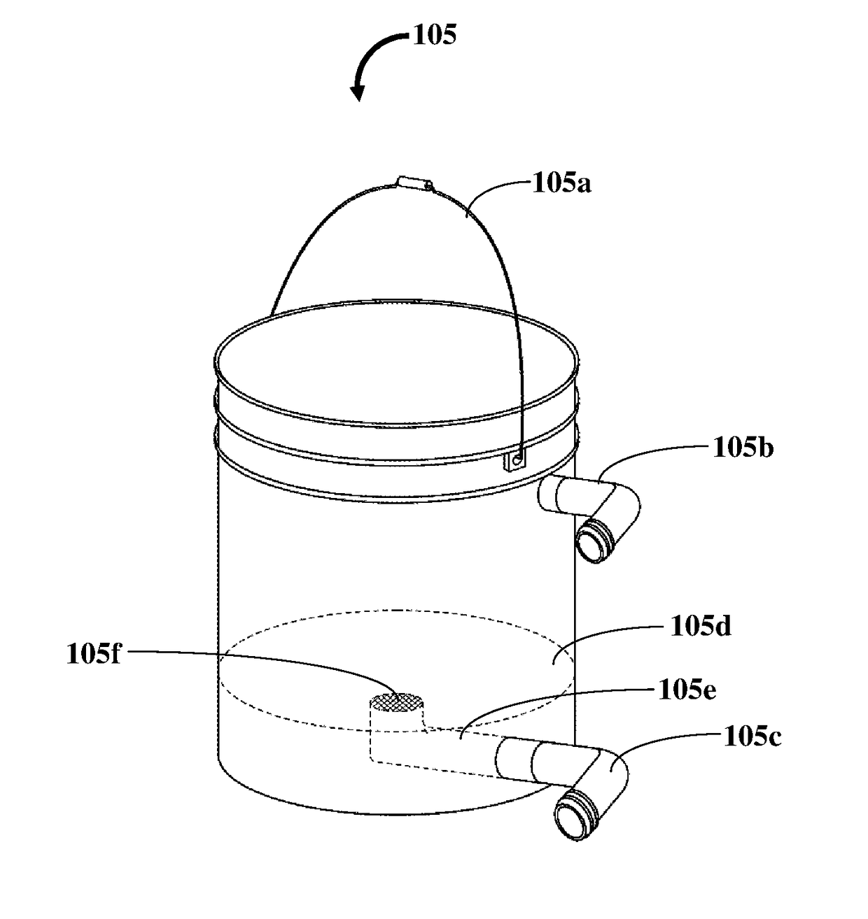
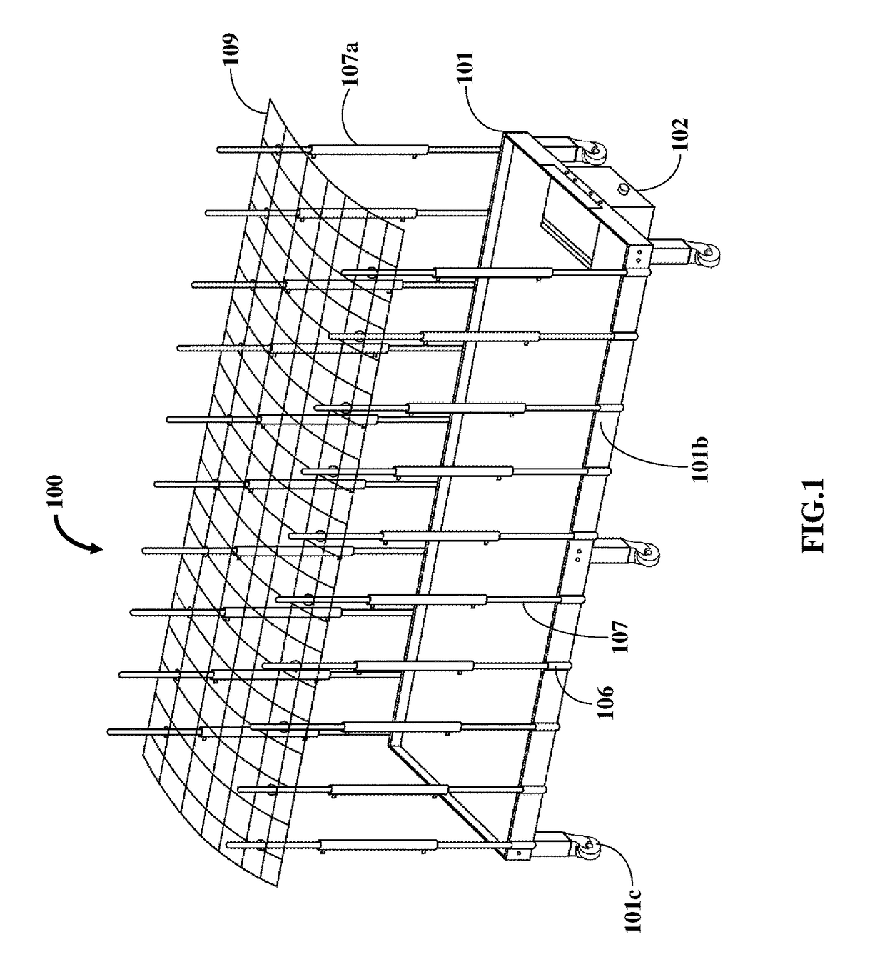
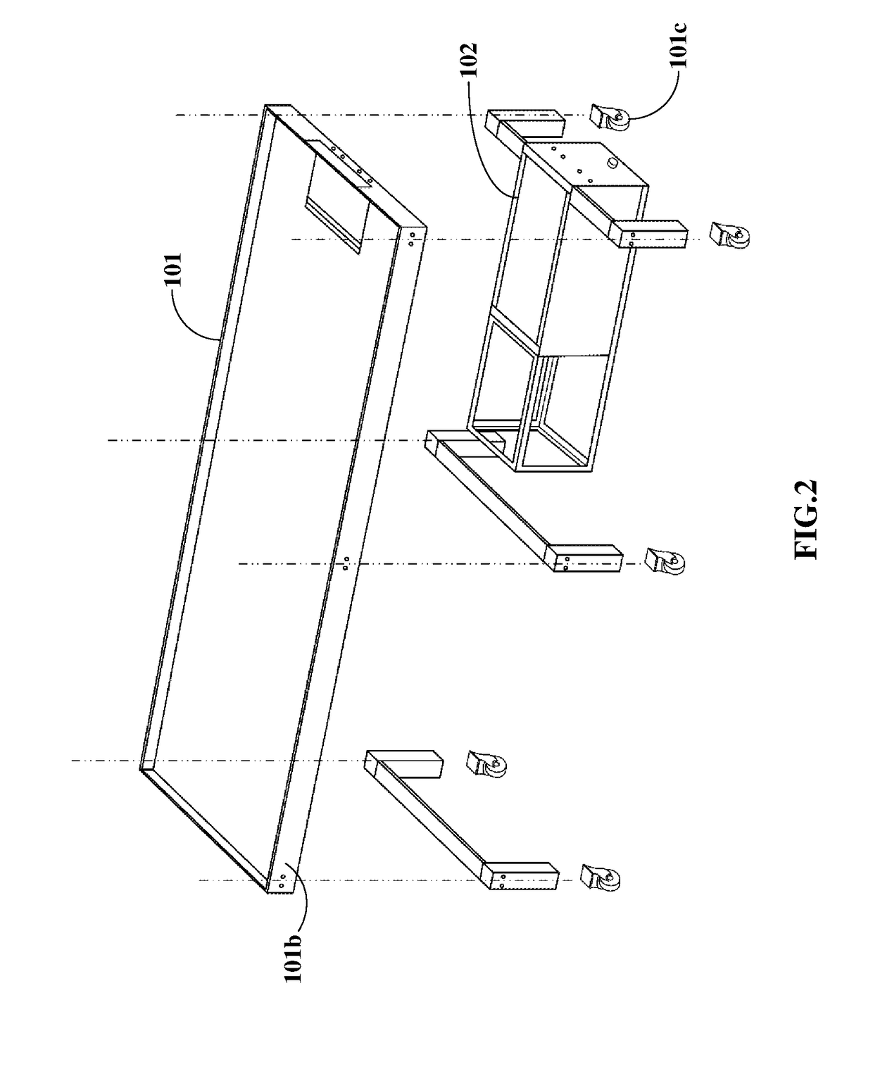
[0018]FIG. 1 exemplarily illustrates a perspective view of an industrial hydroponic control apparatus 100. FIG. 2 exemplarily illustrates an exploded view of an industrial hydroponic control apparatus. The industrial hydroponic control apparatus for monitoring and modifying an environment for growing plants comprises a portable table 101, a reservoir 102, a refrigerator assembly 103, and a control device 104 as exemplarily illustrated in FIGS. 1-8. The portable table 101 comprises predetermined positions 101a for mounting a plurality of insulated plant containers 105 exemplarily illustrated in FIG. 6. Each insulated plant container 105 supports one or more plants. The portable table 101 comprises mounting sleeves 106, vertical posts 107, circular cage members 108, and a roof cage member 109 as exemplarily illustrated in FIGS. 1, 2, 5, and 6. In an embodiment, the mounting sleeves 106 are fixedly attached to external side surfaces 101b of the portable table 101. In an embodiment, cas...


PUM


Abstract

An industrial hydroponic control apparatus for monitoring and modifying an environment for growing plants includes a portable table, a reservoir, a refrigerator assembly, and a control device. The portable table includes predetermined positions for mounting insulated plant containers (IPC). Each IPC supports one or more plants. The reservoir is positioned below the portable table. The reservoir is in fluid communication with each IPC to distribute a fluid to each IPC and drain the excess fluid from each IPC via a piping network. The refrigerator assembly is positioned adjacent to the reservoir and is operably engaged to the reservoir. The refrigerator assembly adjusts a temperature of the fluid within a predefined range, thereby chilling the fluid. The control device is in operable communication with the IPC, the refrigerator, and the reservoir. The control device is configured for monitoring and modifying the environment for growing the plants.

Description

FIELD OF THE INVENTION[0001]The invention disclosed herein relates generally to growing plants using hydroponic gardening apparatuses. More particularly, the invention relates to a hydroponic gardening apparatus, which is portable, capable of growing plants with minimal human interaction, and capable of interfacing with horticulture tracking software.BACKGROUND[0002]Hydroponics refers to the method of growing plants without soil. Instead, the plants are grown using aerated stones and fed with mineral nutrient solutions. Conventional hydroponics systems used for indoor or industrial gardening applications require skilled labor for installation. Additionally, these systems lack portability thereby reducing their utility in applications requiring frequent movement of the hydroponic gardening equipment. A hydroponic gardening apparatus, which is portable and installed with minimum effort, is required. Furthermore, existing hydroponic systems do not provide feedback to a user in the even...

Claims


Application Information

Patent Timeline
IPC IPC(8): A01G31/02A01G9/24A01G13/02F25D17/02F25D11/00F25D19/00G06F3/14G05B19/042
CPCA01G31/02G05B2219/2625A01G13/0243A01G13/0212A01G9/247F25D17/02F25D11/00F25D19/003G06F3/14G05B19/0428A01G2031/006F25D2317/0411F25D2400/361G06F3/0488A01G9/246Y02A40/25Y02P60/21
Inventor BILLINGS, SCOTT
Owner BILLINGS SCOTT
Why Eureka
Try Eureka