
Bag filter filtration and dust collecting apparatus for preventing dust accumulation

a bag filter and dust collector technology, applied in the direction of transportation and packaging, human health protection, separation processes, etc., can solve the problems of increased pressure loss, clogging of the outlet end, and thicker dust layers trapped in the filter cloth, so as to prevent dust build-up on the wall of the effect of efficiently maintaining the bag filter dust collector

Active Publication Date: 2018-03-08
LG CHEM LTD
View PDF1 Cites 2 Cited by
  • Summary
  • Abstract
  • Description
  • Claims
  • Application Information

AI Technical Summary

Benefits of technology

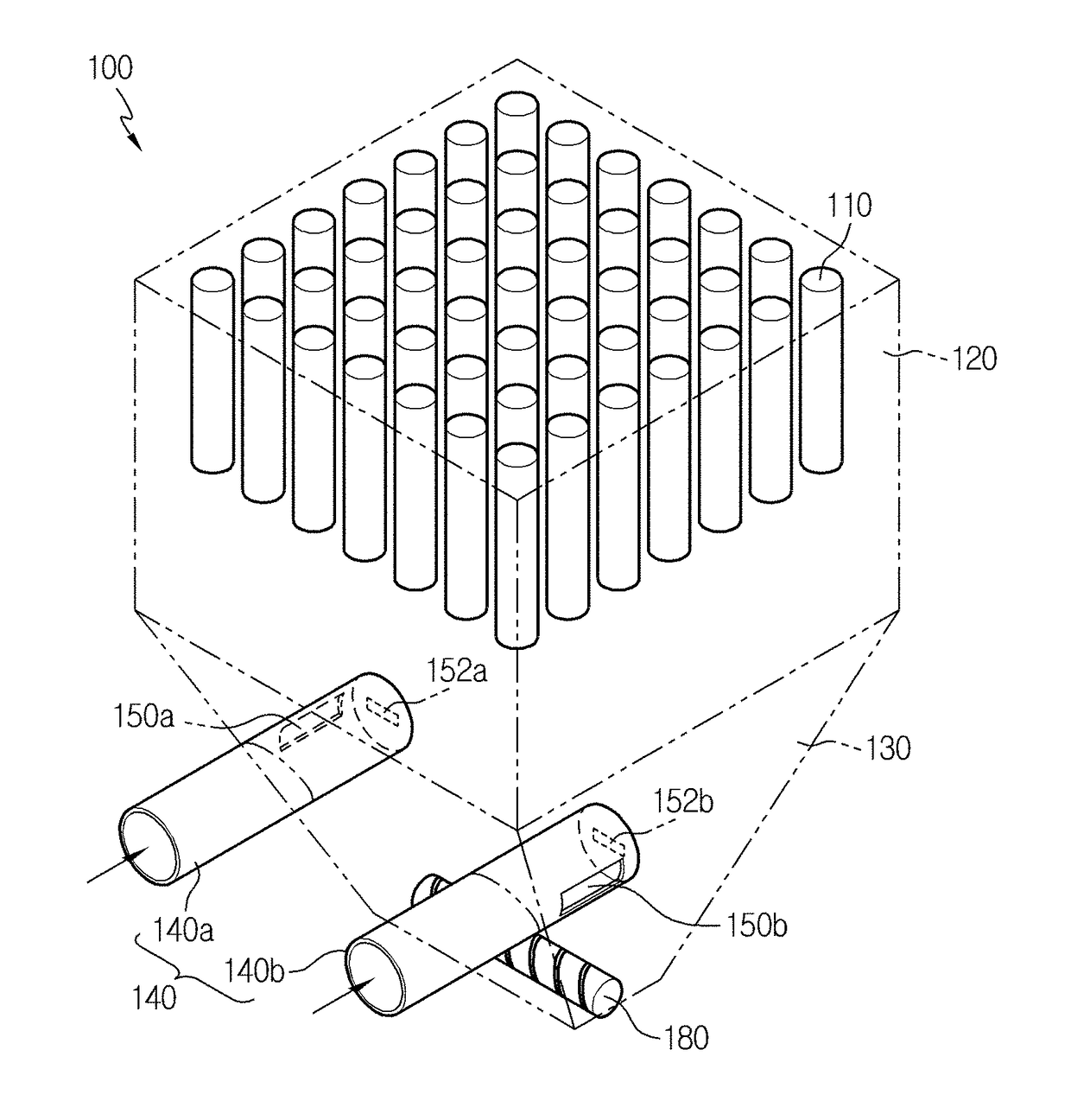
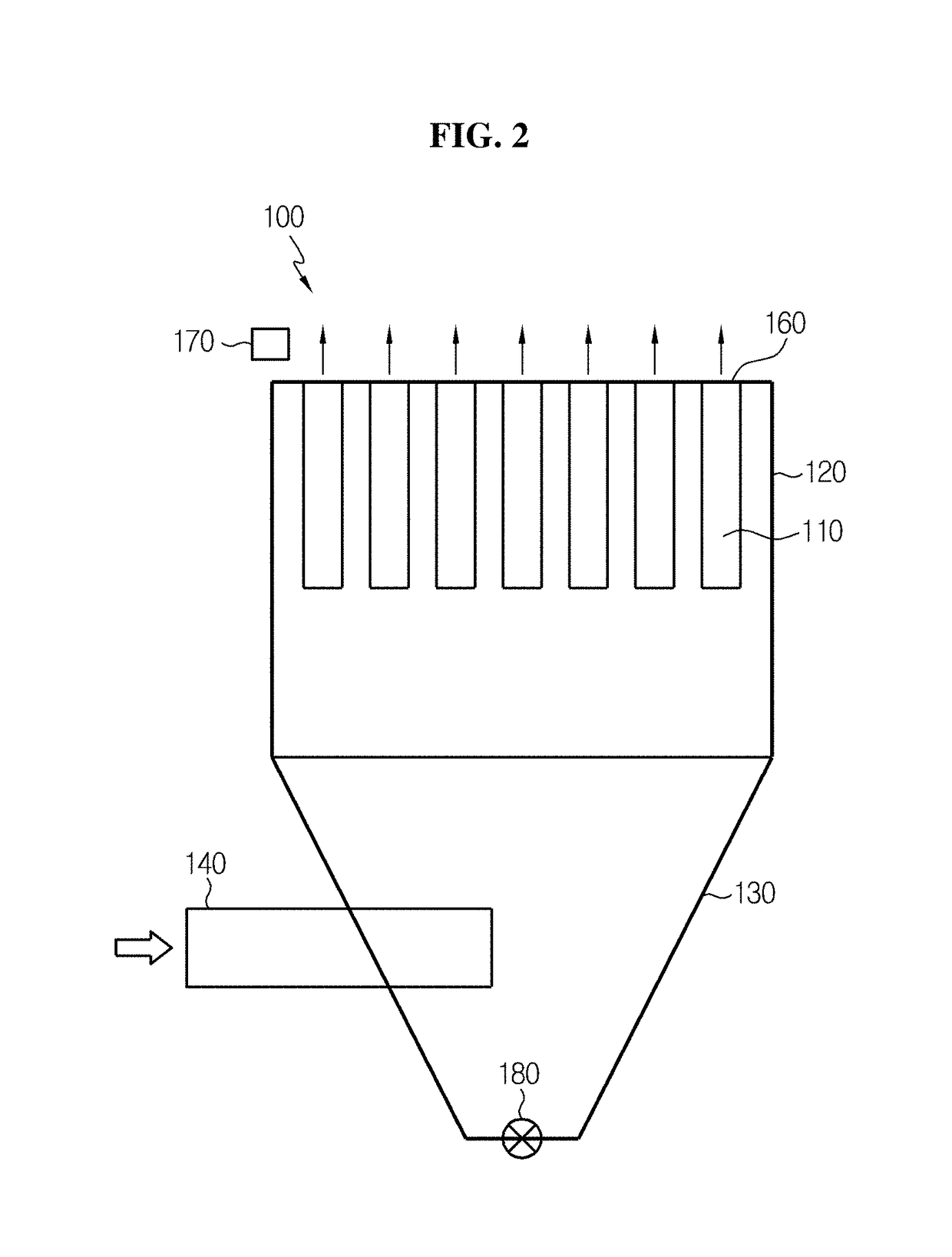
The present patent describes a new design for a bag filter dust collector that prevents dust build-up on the inner wall of the filter. This is achieved by directing air blast towards the side surface of the filter, creating a dust fall zone at the central space between the air supply pipes. The design prevents damage or injury to adjacent facilities and saves maintenance and repair costs. It also reduces the need for periodic cleaning and prevents dust re-scattering.

Problems solved by technology

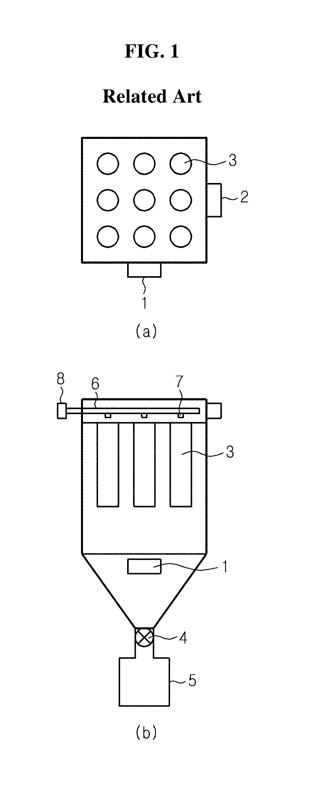
The bag filter dust collector has high dust collection efficiency, but in the course of filtering, dust layers trapped in a filter cloth become thicker and a pressure loss increases, so it is necessary to blow dust on the surface of the bag filter by periodic cleaning operation.
However, while dust is falling, some may be attached to the inner wall, and if dust build-up on the inner wall continues and is not properly removed, an outlet may be clogged in the end.
To solve the problem, an air knocker or a vibrator is generally used, and in this case, there is a dedusting effect at certain areas, but adjacent facility is damaged by vibration.

Method used


Image

  • Bag filter filtration and dust collecting apparatus for preventing dust accumulation
  • Bag filter filtration and dust collecting apparatus for preventing dust accumulation
  • Bag filter filtration and dust collecting apparatus for preventing dust accumulation

Examples


Embodiment Construction

[0046]Hereinafter, the preferred embodiments of the present disclosure will be described in detail with reference to the drawings. However, the present disclosure is not limited to the disclosed embodiment and will be embodied in different forms, and rather, these embodiments are provided to render the disclosure of the present disclosure complete and to help those skilled in the art fully understand the scope of the present disclosure. The embodiments stated herein and illustration in the drawings are just a most preferred embodiment of the present disclosure and do not fully represent the technical concept of the present disclosure, so it should be understood that there may be various equivalents and modifications for alternative embodiments at the time the application is filed.

[0047]FIG. 2 is a side cross-sectional view of a bag filter dust collector according to an embodiment of the present disclosure, and FIG. 3 is a perspective view of a bag filter dust collector according to ...


PUM

PropertyMeasurementUnit
Angleaaaaaaaaaa
Angleaaaaaaaaaa
Angleaaaaaaaaaa

Abstract

A bag filter filtration and dust collecting apparatus according to the present invention is a bag filter filtration and dust collecting apparatus using a bag filter for collecting dust and the like from supplied polluted air and then discharging the dust and the like to the outside, and the bag filter filtration and dust collecting apparatus comprises: an upper case in which a plurality of bag filters for filtering dust are installed in the vertical direction; a lower case, formed at a lower end of the upper case, which collects dust that falls from the bag filter; and at least two mutually parallel air supply pipes, passing through the lower case, which supply polluted air into the bag filter filtration and dust collecting apparatus, wherein the air supply pipe is provided with a side discharge hole formed on the side thereof whereby the air spray is directed toward the inner side wall of the upper case or the lower case, and accordingly, a central space between the at least two air supply pipes forms a region in which dust can fall.

Description

TECHNICAL FIELD[0001]The present disclosure relates to a bag filter dust collector used to trap particulate contaminants including dust released from various types of industrial facilities, and more particularly, to a bag filter dust collector that can solve the problem with dust accumulated and left un-dislodged on the inner wall. The present application claims priority to Korean Patent Application No. 10-2015-0105783 filed in the Republic of Korea on Jul. 27, 2015, the disclosure of which is incorporated herein by reference.BACKGROUND ART[0002]Generally, exhaust gases released from various types of industrial facilities include fine particles. To remove particulate contaminants from exhaust gases, devices such as a cyclone and a bag filter dust collector are used. When exhaust gases pass through the cyclone, larger and heavier dust is captured, and un-captured smaller and lighter dust is collected by the bag filter dust collector. The bag filter dust collector is designed to separ...

Claims


Application Information

Patent Timeline
IPC IPC(8): B01D46/02B01D46/04B01D46/48
CPCB01D46/023B01D46/04B01D46/48B01D46/4227B01D46/72B01D46/02B01D46/0043Y02A50/2351B01D46/56B01D46/58
Inventor KIM, HYUNG-SOPPARK, WON-CHANBAEK, YONG-JINWON, JONG-OH
Owner LG CHEM LTD
Learn More