

Moving vehicle
- Summary
- Abstract
- Description
- Claims
- Application Information
AI Technical Summary
Benefits of technology
Problems solved by technology
Method used
Image

Examples
embodiment 2
[0119]FIGS. 7A and 7B are views illustrating a schematic configuration of an electric motor vehicle chassis in Embodiment 2 of a moving vehicle of the disclosure, FIG. 7A is a left side view, and FIG. 7B is a sectional view taken along line VIIB-VIIB of FIG. 7A. In FIGS. 7A and 7B, elements which are the same as the elements in FIG. 1A to FIG. 5 will be assigned with the same reference signs.
[0120]Hereinafter, points of Embodiment 2 that are different from those of Embodiment 1 will generally be described.
[0121]A moving vehicle 1B of Embodiment 2 includes an electric motor vehicle chassis 10B that is formed by providing the electric motor vehicle chassis 10A in the moving vehicle 1A of Embodiment 1 with a right power transmission mechanism 45R which connects the front and rear wheels 21 and 22 on the right together and a left power transmission mechanism 45L which connects the front and rear wheels 31 and 32 on the left together.
[0122]That is, the moving vehicle 1B of Embodiment 2 h...
embodiment 3
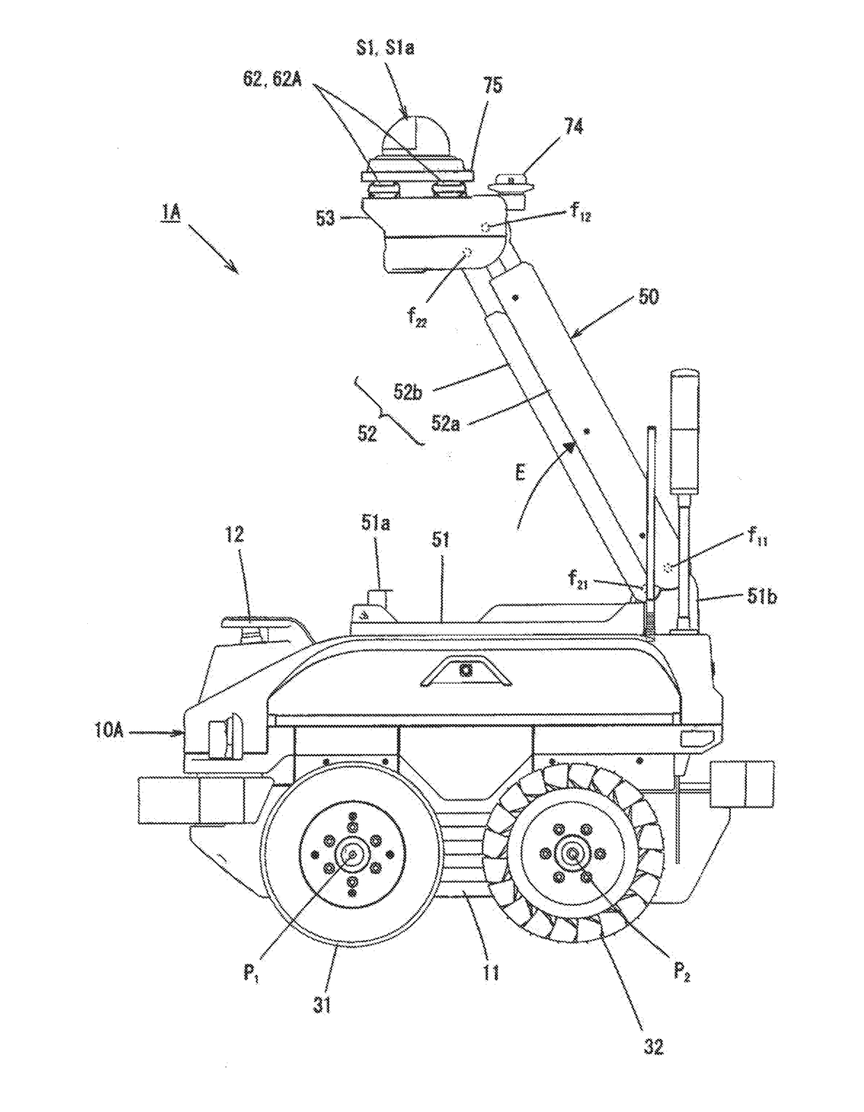
[0134]FIG. 8 is a left side view illustrating a moving vehicle of Embodiment 3, and FIG. 9 is a left side view illustrating an imaging unit raised state in the moving vehicle of FIG. 8. In FIGS. 8 and 9, elements which are the same as the elements in FIG. 2 will be assigned with the same reference signs.
[0135]A moving vehicle 1C of Embodiment 3 is mostly the same as the moving vehicle 1A of Embodiment 1 except that an elevating mechanism 50 which, raises and lowers the imaging unit S1a is included.
[0136]Hereinafter, portions of Embodiment 3 that are different from, those of Embodiment 1 will generally be described.
[0137]As illustrated in FIGS. 8 and 9, a link mechanism that has a boom 52 which swings in the up-and-down and in the front-and-rear direction, specifically, a parallel link mechanism is used as the elevating mechanism 50 in Embodiment 3.
[0138]That is, the elevating mechanism 50 includes an underframe 51 that is fixed onto the chassis body 11 and extends in the front-and-r...
modification example 1 of embodiment 3
[0152]FIG. 10 is a left side view illustrating Modification example 1 of a moving vehicle of Embodiment 3,and FIG. 11 is a left side view illustrating an imaging unit raised state in the moving vehicle of FIG. 10. In FIGS. 10 and 11, elements which are the same as the elements in FIG. 2 will be assigned with the same reference signs.
[0153]The moving vehicle 1C of Embodiment 3 illustrated in FIGS. 8 and 9 may use an elevating mechanism illustrated in FIGS. 10 and 11.
[0154]A single-arm-type pantograph mechanism is used as an elevating mechanism 150 in a moving vehicle 1D of Modification example 1 illustrated in FIGS. 10 and 11.
[0155]That is, the elevating mechanism 150 includes an underframe 151 that is fixed onto the chassis body 11 and extends in the front-and-rear direction, a first boom 152A provided on a front end portion 151b of the underframe 151 so as to be swingable around a right-left shaft center, a second boom 152B provided on a tip portion of the first boom 152A so as to ...
PUM
 Abstract
Description
Claims
Application Information