
Marine Utility Cast Iron Anode

a technology of cast iron anode and marine environment, applied in the field of anodes, can solve the problems of cathodic protection system failure, corrosion of submerged metallic surfaces of pipelines and other structures in the marine environment, and failure of anode sleds, etc., and achieves improved reliability, increased active surfaces, and high surface to weight ratio

Active Publication Date: 2018-03-08
MOGHBELI OMIDREZA
View PDF3 Cites 0 Cited by
  • Summary
  • Abstract
  • Description
  • Claims
  • Application Information

AI Technical Summary

Benefits of technology

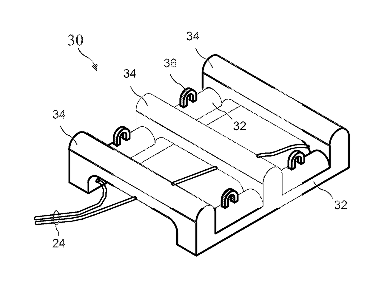
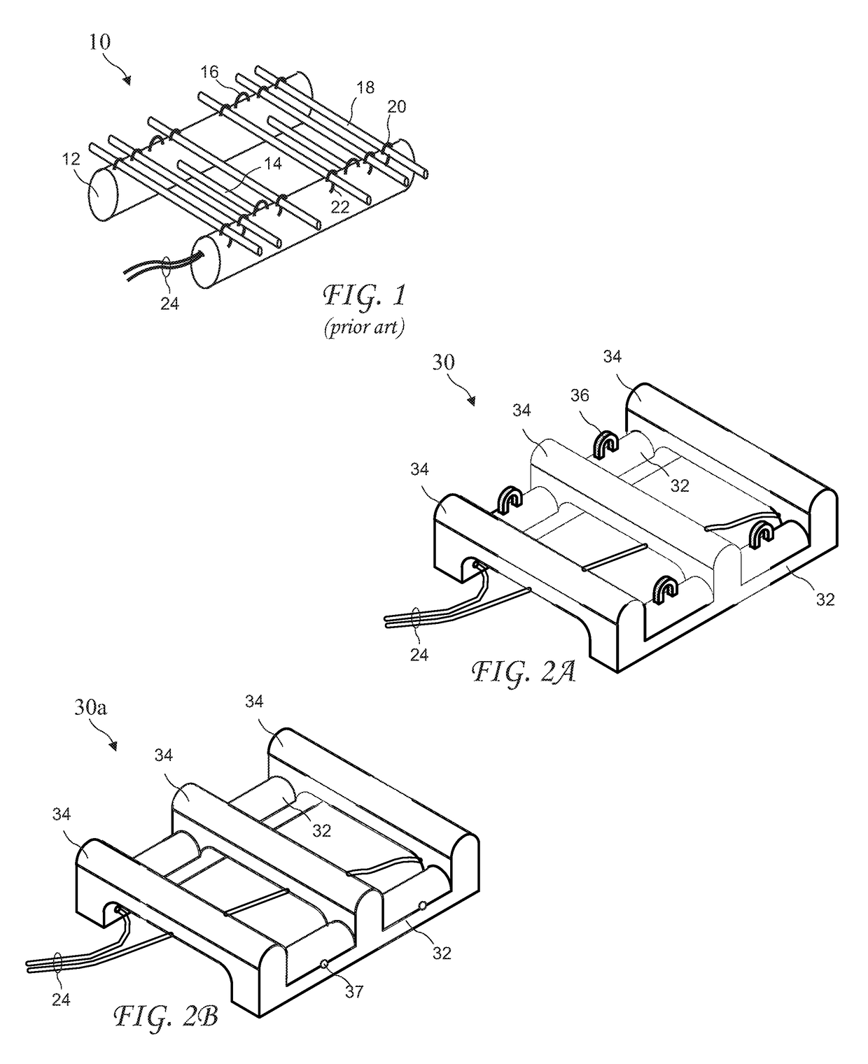
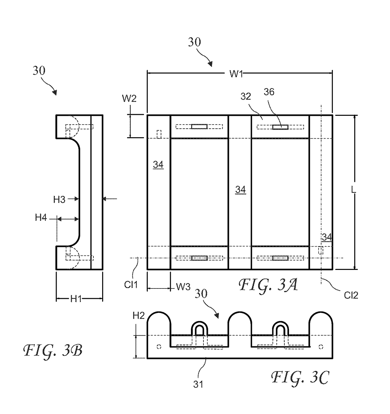
The present invention is an improved marine anode sled that is made from a single piece casting that increases the surface area and reliability of the sled. It has a high surface to weight ratio, meaning it has more active surfaces. Compared to existing anode sleds with similar weight, the new anode has significantly higher current output. The single piece casting eliminates structural and electrical failures that can occur with known anode sleds. The new anode sled has two redundant lead cables attached to opposite corners, which optimizes reliability and electrical performance.

Problems solved by technology

Submerged metallic surfaces of pipelines and other structures in marine environment are subject to corrosion due to electrochemical reactions between the metallic surfaces and seawater they are in contact with.
Impressed current cathodic protection systems are excessively used in marine environment employ a series of anodes at the sea or ocean bottom in order to mitigate and control the severity of corrosion attacks.
As a result, the submerged anode system placed at the ocean or sea floor must be heavy enough to prevent any movement and subsequent failure.
Damage to any of the cables or clamps can result in failure of the anode sled.
Current output capacity and efficiency of each cathodic protection anode in a specific medium is limited by the surface area of the anode.

Method used


Image

  • Marine Utility Cast Iron Anode
  • Marine Utility Cast Iron Anode
  • Marine Utility Cast Iron Anode

Examples


Embodiment Construction

[0018]The following description is of the best mode presently contemplated for carrying out the invention. This description is not to be taken in a limiting sense, but is made merely for the purpose of describing one or more preferred embodiments of the invention. The scope of the invention should be determined with reference to the claims.

[0019]Where the terms “about” or “generally” are associated with an element of the invention, it is intended to describe a feature's appearance to the human eye or human perception, and not a precise measurement.

[0020]A prior art marine anode sled 10 is shown in FIG. 1. The anode sled 10 includes a frame comprising two large diameter concrete longitudinal beams 12 connected by smaller lateral beams 14, and four lifting eyes 16. A plurality of anodes 18 are attached to the beams 12 by loops 20. One or two electrical cable connections 22 connect to each cathodic protection anode 18, anode clamps 20 attach the cathodic protection anodes 18 to frame, ...


PUM


Abstract

An improved marine anode sled comprises a single piece casting with high surface to weight ratio providing increased active surfaces and improved reliability. In one embodiment the anode weighs about 2,000 lbs and has an active surface area of about 5,000 square inches and a current output capacity of up to 160 amps. The improved anode has considerably higher current output than existing anode sleds with similar weight. Unlike known anode sleds, the entire exposed surface of new anode sled is anode material and passes current to a surrounding medium. The single piece casting eliminates structural failure when a frame of know anode sleds is damaged, and electrical failure when cables connecting multiple anodes are damaged. Two redundant lead cable are attached proximal to opposite corners to optimize reliability and electrical performance.

Description

CROSS-REFERENCE TO RELATED APPLICATIONS[0001]The present application claims the priority of U.S. Provisional Patent Application Ser. No. 62 / 384,042 filed Sep. 6, 2016, which application is incorporated in its entirety herein by reference.BACKGROUND OF THE INVENTION[0002]The present invention relates generally to anodes being utilized in impressed current cathodic protection system of marine submerged pipelines and structures.[0003]Submerged metallic surfaces of pipelines and other structures in marine environment are subject to corrosion due to electrochemical reactions between the metallic surfaces and seawater they are in contact with. Cathodic protection systems are installed to limit the amount of corrosion occurring on the subjected surfaces. Impressed current cathodic protection systems are excessively used in marine environment employ a series of anodes at the sea or ocean bottom in order to mitigate and control the severity of corrosion attacks. One of the most common anode ...

Claims


Application Information

Patent Timeline
IPC IPC(8): C23F13/10C23F13/20
CPCC23F13/20C23F13/10C23F2213/31
Inventor MOGHBELI, OMIDREZA
Owner MOGHBELI OMIDREZA
Learn More