
Projection image display device

a technology of projection image and display device, which is applied in the direction of lighting and heating apparatus, semiconductor devices for light sources, instruments, etc., can solve the problems of lowering the brightness of a projected image in association with a change in color temperature, and achieve the effect of inhibiting the brightness of a projected image from being lowered and the color temperature being lower

Active Publication Date: 2018-03-08
JVC KENWOOD CORP A CORP OF JAPAN
View PDF3 Cites 5 Cited by
  • Summary
  • Abstract
  • Description
  • Claims
  • Application Information

AI Technical Summary

Benefits of technology

The present invention provides a technology for a projection image display device that can switch between a mode with high color temperature and a mode with low color temperature. This technology allows for lowering color temperature without reducing the brightness of projected images.

Problems solved by technology

In a case where a dark filter is used to lower the color temperature as in the projector of patent document 1, there is a problem in that the brightness of a projected image is lowered in association with a changed the color temperature.

Method used


Image

  • Projection image display device
  • Projection image display device
  • Projection image display device

Examples


Embodiment Construction

[0021]The invention will now be described by reference to the preferred embodiments.

[0022]This does not intend to limit the scope of the present invention, but to exemplify the invention.

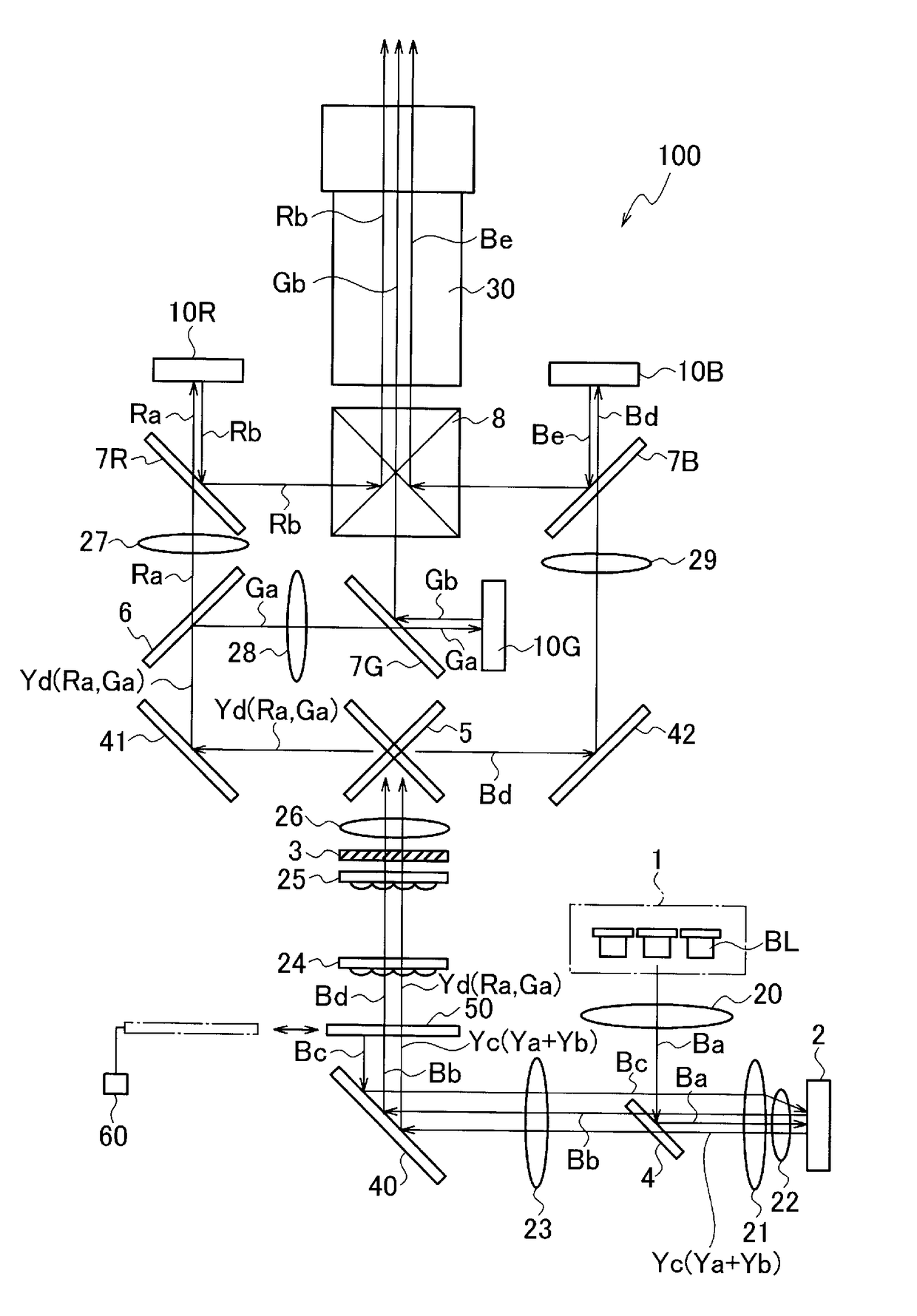
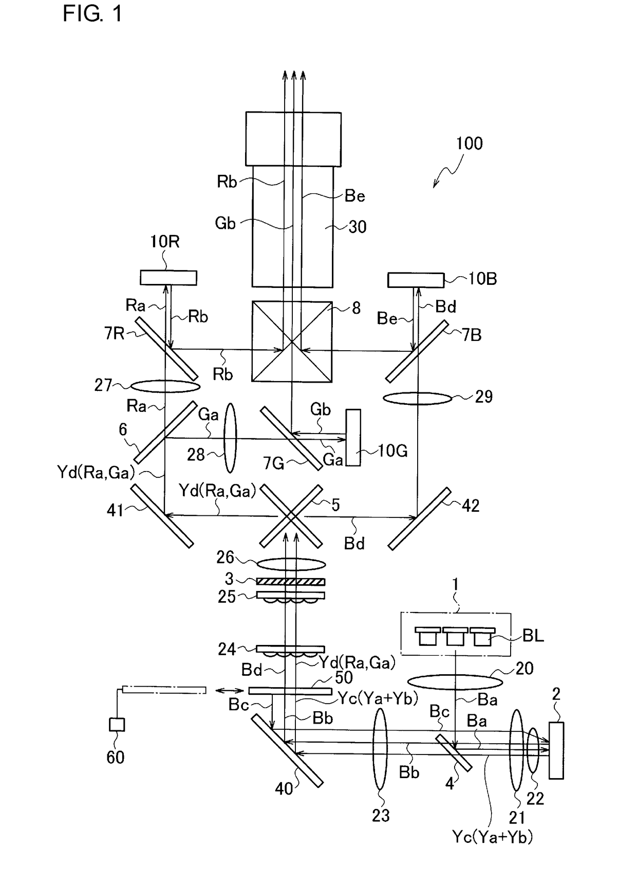
[0023]A description will be given of a projection image display device according to an embodiment with reference to FIG. 1. FIG. 1 shows the overall configuration of the projection image display device according to the embodiment.

[0024]A projection image display device 100 includes a light source 1, a phosphor 2, a polarization conversion system (PCS) 3, dichroic mirrors 4-6, reflective polarization plates 7R, 7G, 7B, a color composition prism 8, image display devices 10R, 10G, 10B, lenses 20-30, reflecting mirrors 40-42, a filter 50, and a motor 60.

[0025]For example, the light source 1 is comprised of a laser array in which a plurality of blue laser devices BL are arranged. The light source 1 emits a blue laser light. The blue laser light will be referred to as a blue illumination light in the foll...


PUM


Abstract

A projection image display device includes: a light source that emits a blue illumination light; a phosphor that produces, in a region irradiated by the blue illumination light, a yellow illumination light including a component in a red band and a component in a green band from a portion of the blue illumination light and that reflects the blue illumination light and the yellow illumination light; and a filter that reflects a portion of the blue illumination light reflected by the phosphor toward the phosphor. The filter reflects the portion of the blue illumination light so as to be imaged at a position displaced from a region on a phosphor surface irradiated by the blue illumination light, and the phosphor produces a yellow illumination light also from the blue illumination light reflected by the filter.

Description

BACKGROUND OF THE INVENTION1. Field of the Invention[0001]The present invention relates to a projection image display device.2. Description of the Related Art[0002]In a projection image display device, a blue laser light source or a yellow phosphor is used as an illumination source, for example. A blue light image is produced by using a blue laser light source as an illumination source. A red light image and a green light image are produced by using a yellow phosphor as an illumination source. More specifically, the yellow phosphor is irradiated by a laser light from the blue laser light source and converts the energy of the irradiating laser light into a yellow light of a wavelength band including a red band and a green band.[0003]Patent document 1 discloses a projector in which switching between a mode of high color temperature such as 7500 K and a mode of low temperature is implemented by a dark filter, the high color temperature mode being used when brightness is a major concern...

Claims


Application Information

Patent Timeline
IPC IPC(8): G03B21/20G02B27/14F21K9/60F21V7/00
CPCG03B21/2033G02B27/141G02B26/007F21V7/0066F21K9/60G02B27/149G03B21/204G03B33/12
Inventor KIKUMA, SHINJIAIZAKI, TAKATSUGUARIHARA, YASUKI
Owner JVC KENWOOD CORP A CORP OF JAPAN
Learn More