Model predictive control device, control method of model predictive control device, information processing program and recording medium

a control device and model technology, applied in adaptive control, process and machine control, instruments, etc., can solve problems such as large operation load

Active Publication Date: 2018-03-08
ORMON CORP
View PDF7 Cites 2 Cited by
  • Summary
  • Abstract
  • Description
  • Claims
  • Application Information

AI Technical Summary

Benefits of technology

[0017]According to the structure, the predictive value correcting part corrects the predictive value in the action cycle next to a certain action cycle by using the model predictive error in the certain action cycle
[0018]Herein, when the error computing part computes the model predictive error in the certain action cycle, it can be considered that a possibility that the same model predictive error occurs in the action cycle next to the certain action cycle is high.
[0019]Therefore, the model predictive control device achieves the following effects of computing that the possibility of the model predictive error similar to that computed in the certain action cycle is high and correcting the predictive value in the action cycle next to the certain action cycle by using the model predictive error in the certain action cycle.
[0020]Preferably, the model predictive control device further comprises: a torque computing part, computing a torque required by the predictive value corrected by the predictive value correcting part to follow the command value; and a torque command part, outputting the torque computed by the torque computing part as a command value related to torque control of the controlled object to a control system performing motion control over the controlled object.
[0021]According to the structure, the torque computing part computes a torque required by the predictive value corrected by the predictive value correcting part to follow the command value; and the torque command part outputs the torque computed by the torque computing part as a command value related to torque control of the controlled object to the control system.
[0022]Therefore, the model predictive control device achieves the following effect of being capable of outputting the torque causing the controlled quantity of the controlled object to follow the command value to the control system without a need to execute an operation processing of converting a change of the controlled quantity caused by the interference into an operating quantity.

Problems solved by technology

However, in the convention technologies as mentioned above, the operation for inferring the size of a shaping interference and applying timing (generation) according to a level of the operating quantity must be independent from the operation for control, as a result, there is a problem of large operation load.

Method used


Image

  • Model predictive control device, control method of model predictive control device, information processing program and recording medium
  • Model predictive control device, control method of model predictive control device, information processing program and recording medium
  • Model predictive control device, control method of model predictive control device, information processing program and recording medium

Examples


embodiment 1

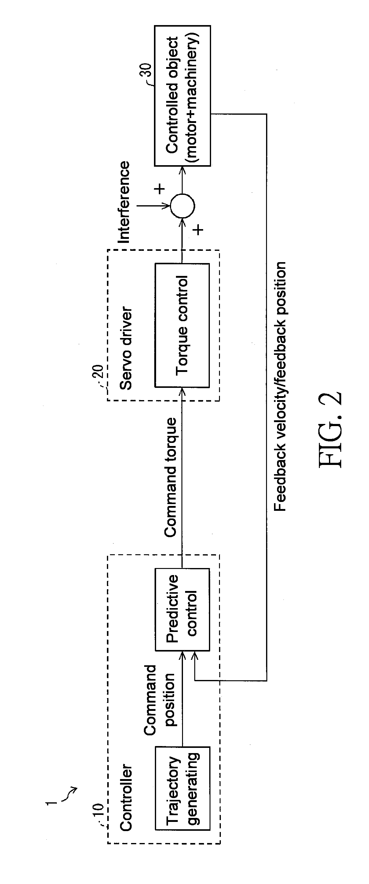
[0049]Embodiment 1 of the present invention is explained in detail based on FIGS. 1-10. The same or equivalent parts are labelled with the same sign and are not explained repeatedly. In order to facilitating understanding on a controller 10 (model predictive control device) in one form of the present invention, at first, FIG. 2 is used to explain a summary of a control system 1 containing the controller 10.

[0050](Summary of the Control System)

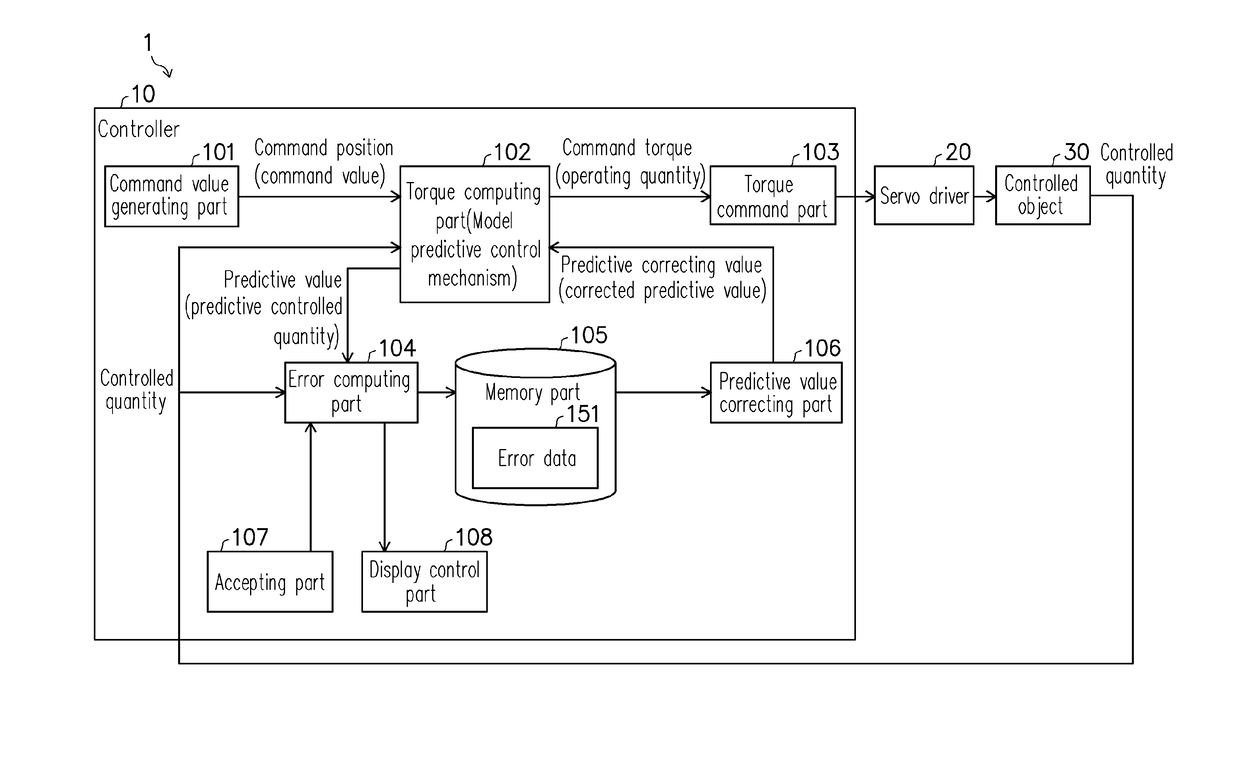
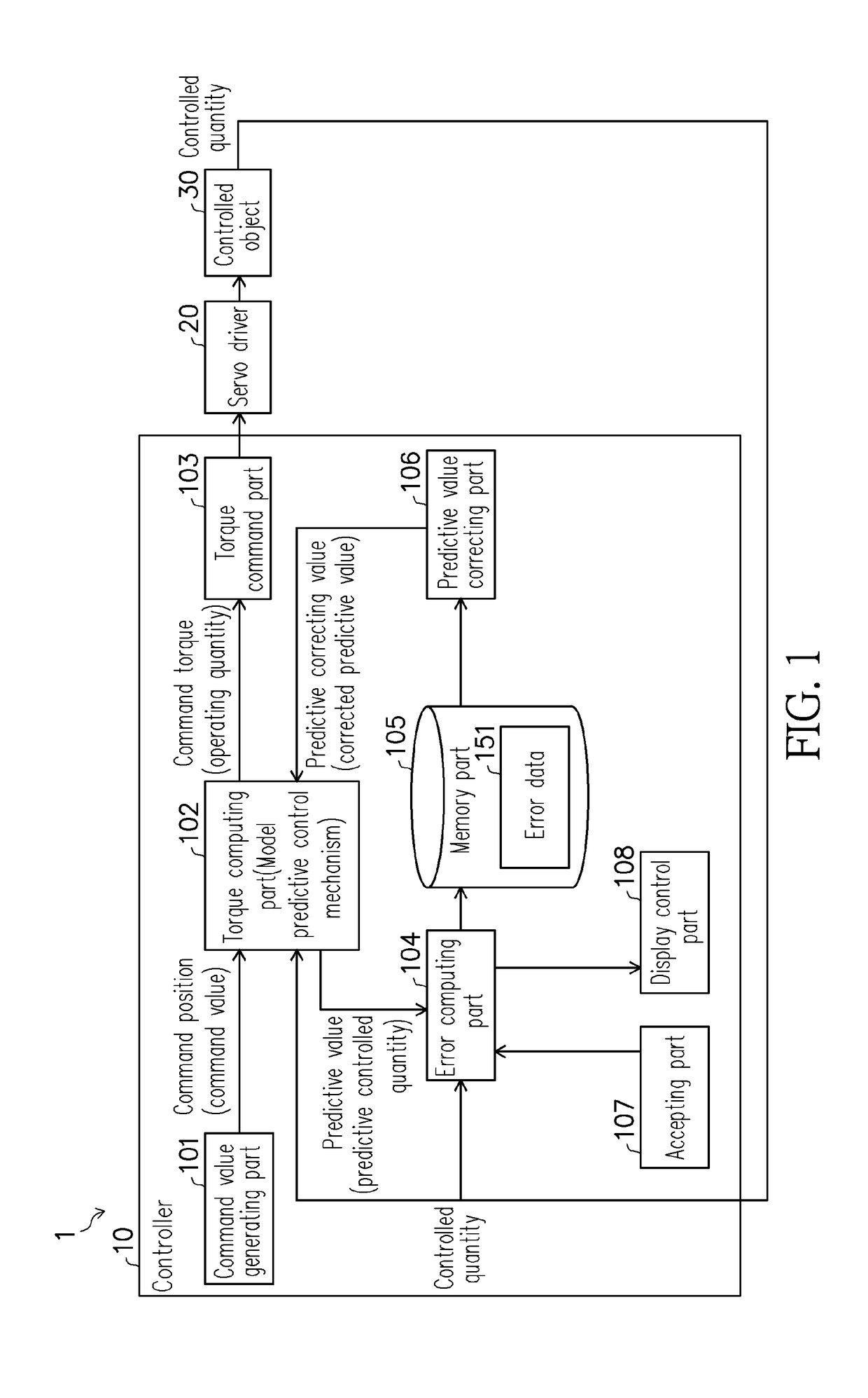
[0051]FIG. 2 is a diagram illustrating a summary of a control system 1 containing the controller 10. The control system 1 is required to inhibit an influence of the interference, i.e., “shaping interference” with the same generating (applying) timing and size in a cycle (one action cycle) on a control performance. Particularly, the controller 10 is required to simplify the processing of compensating the influence for the controlled quantity generated from the shaping interference (interference compensation processing).

[0052]The controller 10 fo...

embodiment

[0196]Another embodiment of the present invention is explained based on FIGS. 11 and 12. In addition, in order to ensure compactness in recording, only the structures (processing process and processed content) different from embodiment 1 are explained. That is, the structures recorded in embodiment 1 can all be contained in the present embodiment. Besides, the meanings of terms recorded in embodiment 1 also the same as those in embodiment 2.

[0197](Summary of a Control System)

[0198]FIG. 12 is a diagram illustrating a summary of a control system 2 containing a controller 100. The control system 2 is different from the control system 1 that executes position / velocity control and outputs the torque command value through predictive control to the servo driver 20 through the controller 10, the controller 100 corrects a command position for a servo driver 120 through predictive control and the servo driver 120 executes position / velocity control. That is, in the control system 1, the contro...


PUM


Abstract

The present invention simplifies the processing for compensating an influence for a controlled quantity generated from shaping interference in motion control. A controller (10) as a model predictive control device computes an error between an actually measured value of a controlled quantity in a certain action cycle when shaping interfering is applied and a predictive value of the controlled quantity in the certain action cycle, i.e., the model predictive error, and corrects the predictive value in the action cycle after the certain action cycle by using the computed model predictive error.

Description

CROSS-REFERENCE TO RELATED APPLICATION[0001]This application claims the priority benefit of Japanese application serial no. 2016-172851, filed on Sep. 5, 2016. The entirety of the above-mentioned patent application is hereby incorporated by reference herein and made a part of this specification.BACKGROUND OF THE INVENTION1. Field of the Invention[0002]The present invention relates to a model predictive control device and so on using a model of a controlled object as a motion controlled object to predict a controlled quantity.2. Description of Related Art[0003]In the past, for example, there is a known interference (shaping interference) generated in a shaping manner in execution of motion control by a contact force change and so on between a tool and a work in a cycle (action cycle), and an influence of the shaping interference on a controlled quantity is tried to be inhibited.[0004]For example, the following patent document 1 records a process control device, which controls a proce...

Claims


Application Information

Patent Timeline
Patent Type & Authority Applications(United States)
IPC IPC(8): G05B13/04
CPCG05B13/048G05B13/042
Inventor NAMIE, MASAKI
Owner ORMON CORP
Why Eureka
Try Eureka