Suspension board with circuit and producing method thereof
Inactive Publication Date: 2018-03-08
NITTO DENKO CORP
View PDF2 Cites 1 Cited by
Summary
Abstract
Description
Claims
Application Information
AI Technical Summary
This helps you quickly interpret patents by identifying the three key elements:
Problems solved by technology
Method used
Benefits of technology
Benefits of technology
The patent text discusses a method of aligning a piezoelectric element using the surface tension of solder material during reflow. This results in an improved position accuracy of the piezoelectric element, allowing for the production of a suspension board with excellent position accuracy and a reduced thickness of the portion where the piezoelectric element is mounted.
Thus, in the suspension described in Japanese Unexamined Patent Publication No. 2014-106993, it is difficult to achieve improvement of the position accuracy of the piezoelectric element, and achieve a reduction in the thickness of the portion on which the piezoelectric element is mounted.
Method used
Image
Click on the blue label to locate the original text in one second.
Reading with bidirectional positioning of images and text.
Examples
second embodiment
3. Second Embodiment
[0171]Next, a second embodiment of the present invention is described with reference to FIG. 10. In the second embodiment, the same reference numerals are provided for members corresponding to each of those in the above-described first embodiment, and their detailed description is omitted.
[0172]In the first embodiment, as shown in FIG. 4A, the size in the front-rear direction of the first terminal 30 with respect to that in the front-rear direction of the first element terminal 40 is 100%, and the size in the front-rear direction of the second terminal 31 with respect to that in the front-rear direction of the second element terminal 41 is 100%, but the ratio is not limited thereto.
[0173]In the second embodiment, as shown in FIG. 10, the front end edge of the first terminal 30 generally coincides with that of the first element terminal 40 in the front-rear direction. The size in the front-rear direction of the first terminal 30 with respect to that in the front-r...
examples
[0179]In the following, the present invention will be described in detail with Examples and Comparative Examples, but the present invention is not limited thereto. The specific numerical values in mixing ratio (content ratio), property value, and parameter used in the following description will be replaced with upper limits (numerical values defined as “or less” or “below”) or lower limits (numerical values defined as “or more” or “above”) of corresponding numerical values in mixing ratio (content ratio), property value, and parameter described in the above-described “DETAILED DESCRIPTION OF THE INVENTION”.
examples 1 to 4
[0180]Suspension boards with circuit, each of which included two pairs of first terminal (size in the front-rear direction of the terminal / size in the front-rear direction of the element terminal: 100%, size in the right-left direction of the terminal / size in the right-left direction of the element terminal: 90%) and second terminal (size in the front-rear direction of the terminal / size in the front-rear direction of the element terminal: 100%, size in the right-left direction of the terminal / size in the right-left direction of the element terminal: 100%), were prepared.
[0181]Next, a Sn—Ag—Cu solder composition (Sn content ratio: remaining portion, Ag content ratio: 3±1 mass %, Cu content ratio: 0.5±0.1 mass %) was disposed on each of the lower surfaces of the first terminal and the second terminal.
[0182]Next, two piezoelectric elements, each of which included a first element terminal and a second element terminal, were prepared, and each of the piezoelectric elements was disposed s...
PUM
Abstract
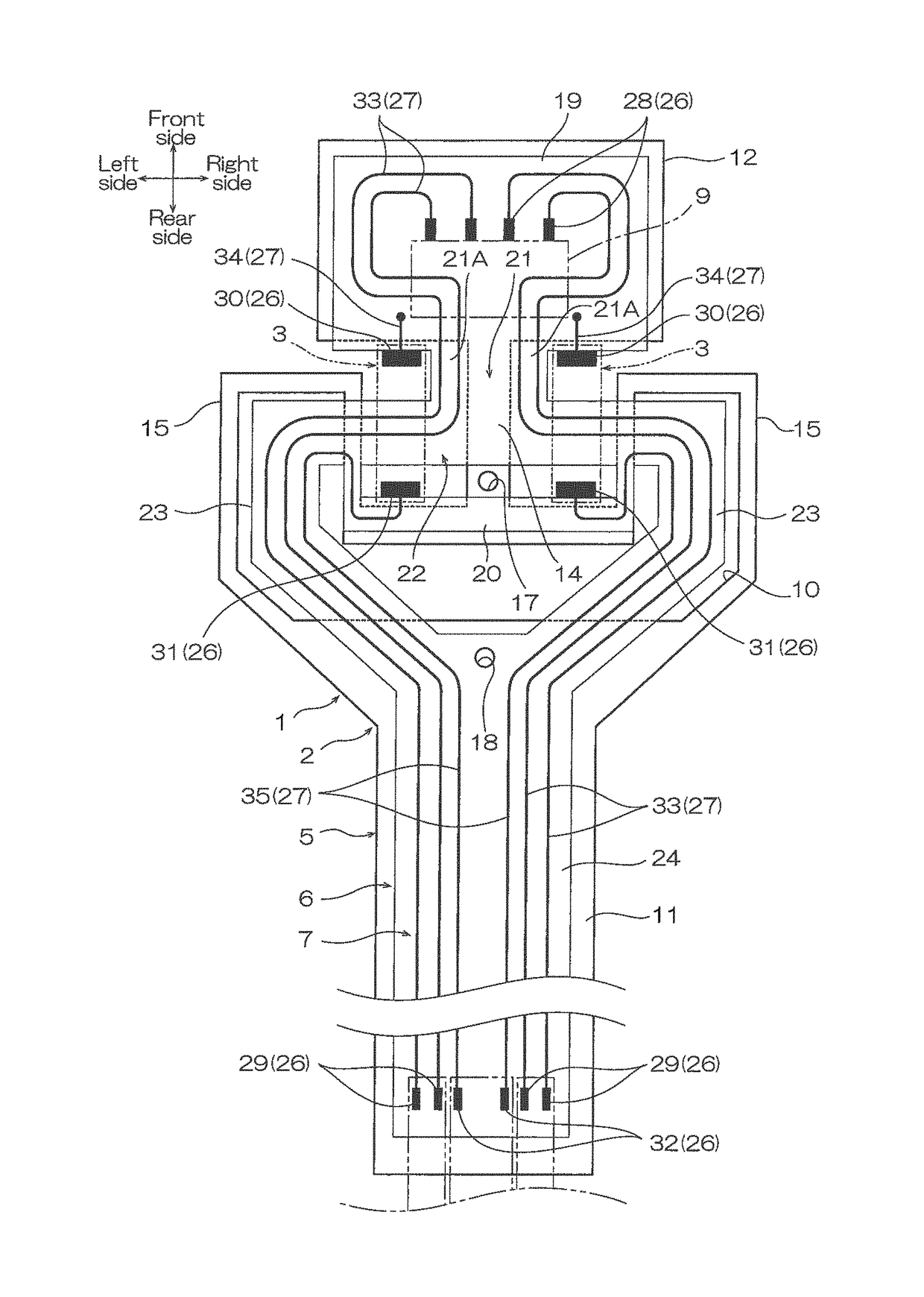
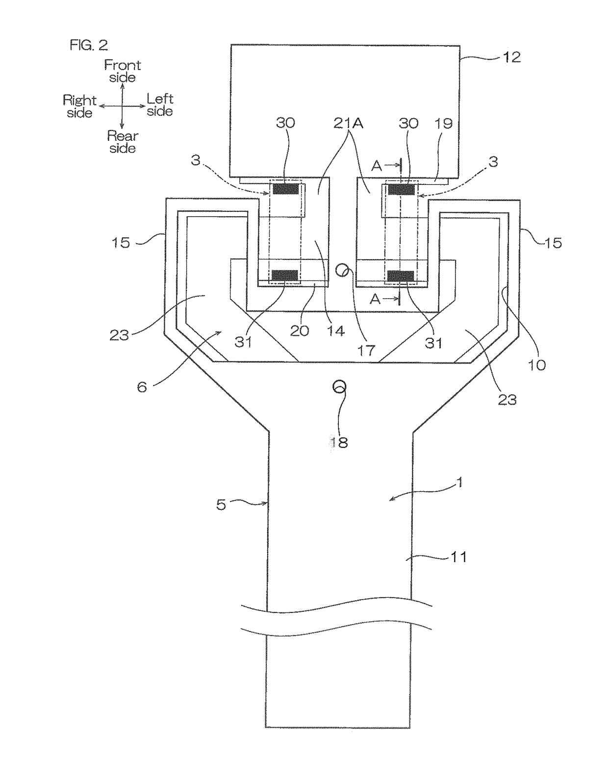
A suspension board with circuit includes a metal supporting layer, a base insulating layer disposed at one side in a thickness direction of the metal supporting layer, a conductive pattern including a wire disposed at one side in the thickness direction of the base insulating layer and a terminal exposed from the metal supporting layer and the base insulating layer when viewed from the other side in the thickness direction, a piezoelectric element disposed at the other side in the thickness direction with respect to the terminal and including an element terminal electrically connected to the terminal, and a solder layer disposed between the terminal and the element terminal. The solder layer has a solder composition containing Sn, Ag, and Cu, and the solder layer has a thickness in the thickness direction of 50 μm or less.
Description
CROSS-REFERENCE TO RELATED APPLICATION[0001]The present application claims priority from Japanese Patent Application No. 2016-174435 filed on Sep. 7, 2016, the contents of which are hereby incorporated by reference into this application.BACKGROUND OF THE INVENTIONField of the Invention[0002]The present invention relates to a suspension board with circuit, and a producing method thereof to be more specific, a suspension board with circuit to be used for a hard disk drive, and a producing method thereof.Description of Related Art[0003]A suspension board with circuit on which a head slider, and a piezoelectric element that is extendable and / or contractable so as to displace the head slider are mounted has been known. The piezoelectric element is connected to a terminal provided in the suspension board with circuit by solder.[0004]For example, a suspension in which a piezoelectric element is connected to an element connecting terminal of a suspension board with a Sn—Bi solder material h...
Claims
Application Information
Patent Timeline
Application Date:The date an application was filed.
Publication Date:The date a patent or application was officially published.
First Publication Date:The earliest publication date of a patent with the same application number.
Issue Date:Publication date of the patent grant document.
PCT Entry Date:The Entry date of PCT National Phase.
Estimated Expiry Date:The statutory expiry date of a patent right according to the Patent Law, and it is the longest term of protection that the patent right can achieve without the termination of the patent right due to other reasons(Term extension factor has been taken into account ).
Invalid Date:Actual expiry date is based on effective date or publication date of legal transaction data of invalid patent.

