
Engine power suppressing device

Active Publication Date: 2018-03-15
KAWASAKI MOTORS LTD
View PDF15 Cites 0 Cited by
  • Summary
  • Abstract
  • Description
  • Claims
  • Application Information

AI Technical Summary

Benefits of technology

The object of the patent is to minimize the uneven distribution of engine power.

Problems solved by technology

Therefore, it becomes possible to reduce the non-uniformity of the amount of the engine power to be suppressed.

Method used


Image

  • Engine power suppressing device
  • Engine power suppressing device
  • Engine power suppressing device

Examples


Embodiment Construction

[0022]Hereinafter, the embodiment of the present invention will be described with reference to the drawings. The directions stated below are from the perspective of a rider in a vehicle. A vehicle length direction conforms to a forward and rearward direction, and a vehicle width direction conforms to a rightward and leftward direction.

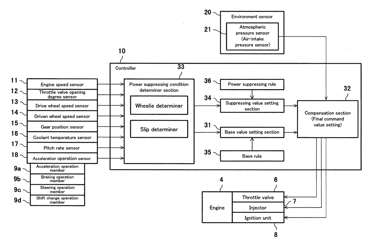
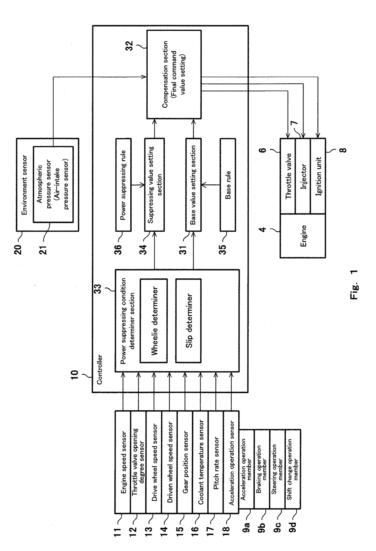
[0023]FIG. 1 shows an engine power suppressing device. The engine power suppressing device is configured to suppress the engine power of an engine 4 mounted in a vehicle as a driving source. Although not shown in detail, a motorcycle is an example of a vehicle in which the engine power suppressing device is mounted. The motorcycle includes one front wheel and one rear wheel. The rear wheel is a drive wheel, and the front wheel is a driven wheel and a steering wheel. Driving power generated in the engine 4 is transmitted to the drive wheel (rear wheel) via a driving power transmission mechanism including a transmission and a clutch. The engine 4 which i...


PUM


Abstract

An engine power suppressing device includes a controller which controls an operation of a power changing element which changes engine power for driving a vehicle; and an environment sensor which detects an environment parameter indicating an environment in which the vehicle is used, wherein the controller determines whether or not a power suppressing condition in which a vehicle state is a state in which the engine power is to be suppressed, is met, wherein in a case where the controller determines that the power suppressing condition is met, the controller sets a suppressing value for the power changing element to suppress the engine power, and compensates the suppressing value based on the environment parameter detected by the environment sensor.

Description

CROSS-REFERENCE TO RELATED APPLICATION[0001]This application claims priority to and the benefit of Japanese Patent Application No. 2016-179706 filed on Sep. 14, 2016, the entire disclosure of which is incorporated herein by reference.BACKGROUND OF THE INVENTION1. Field of the Invention[0002]The present invention relates to an engine power (output) suppressing device.2. Description of the Related Art[0003]An exemplary controller for a vehicle disclosed in JP 2011 137416 A is configured to suppress engine power upon detection of a slip or a wheelie.[0004]In suppressing the engine power, even in a situation in which running parameters (e.g., an engine speed, an air-intake amount, a fuel injection amount, and an ignition timing) of the engine are equal, non-uniformity of the amount of the engine power to be suppressed occurs.SUMMARY OF THE INVENTION[0005]In view of the above, an object of the present invention is to reduce non-uniformity of the amount of the engine power to be suppresse...

Claims


Application Information

Patent Timeline
IPC IPC(8): B60W30/188B60W30/02
CPCB60W30/188B60W30/02B60W2300/36B60W2550/12B60W2720/26B60W2520/26B60W2710/0622B60W2710/0677B60W2555/20
Inventor HIROKAMI, TATSUYATERAI, SHOHEIAZUMA, SEIJIUEDA, KENGO
Owner KAWASAKI MOTORS LTD
Features
  • Generate Ideas
  • Intellectual Property
  • Life Sciences
  • Materials
  • Tech Scout
  • Unparalleled Data Quality
  • Higher Quality Content
  • 60% Fewer Hallucinations
Learn More