Long wave light guide infrared detector non-uniformity correction circuit

A non-uniformity correction and infrared detector technology, which is applied in optical radiation measurement, electric radiation detectors, instruments, etc., can solve the problems of circuit output swing exceeding the dynamic range, uneven resistance, etc., and achieve low power consumption and applicable Wide range and good repeatability

Active Publication Date: 2017-09-22
SHANGHAI INST OF TECHNICAL PHYSICS - CHINESE ACAD OF SCI
View PDF4 Cites 6 Cited by
  • Summary
  • Abstract
  • Description
  • Claims
  • Application Information

AI Technical Summary

Problems solved by technology

[0004] The purpose of the present invention is to provide a non-uniformity on-chip correction circuit for long-wave photoconductive infrared detectors, which solves the problem that the circuit output swing exceeds the dynamic range caused by the uneven resistance of long-wave photoconductive infrared detectors, thereby improving the performance of long-wave photoconductive infrared detectors. system performance level

Method used


Image

  • Long wave light guide infrared detector non-uniformity correction circuit
  • Long wave light guide infrared detector non-uniformity correction circuit
  • Long wave light guide infrared detector non-uniformity correction circuit

Examples


Embodiment approach 1

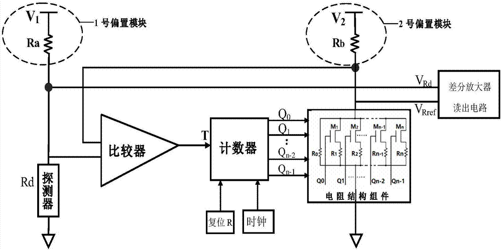
[0025] The unit structure of the correction circuit is as figure 1 Shown, including comparator, counter, resistor structure components and two bias blocks. V can be adjusted according to different detector resistances and resistance structure components 2 Adjustments are made to adjust the voltage division range of the resistive structural components. The voltage source of the bias module should not be too large or too small. If it is too large, the detector will heat up, and if it is too small, the signal of the detector will be small. The resistance of the detector is about 40Ω. When the process error of the resistance structure components is not considered, it can be set, V 1 =2.5V, V 2 = 2.5V, R a =R b = 1KΩ. The specific process of the circuit work is divided into two steps, taking the counter as an example of an addition counter, the first step, the comparator and the counter are powered on, the reset potential and the counting pulse are input, the comparator circu...

Embodiment approach 2

[0034] Let the resistance Rd of a certain detection element be 40Ω, set V 1 =V 2 = 2.5V, R a =R b =1KΩ, using a 7-bit synchronous binary addition counter, at a low temperature of 66K, in the Cadence software environment, using the Specter emulator for simulation, the corresponding correction simulation timing diagram is as follows Figure 5 shown, where the resistive structure component divides the voltage V Rref change process such as Figure 6 As shown, the value of the binary counter after correction is 1010001, and the resistive structure component divides the voltage V Rref It is 95.89mV, which is 0.26mV different from the detector pixel voltage division of 96.15mV. Within the error range, when the detector resistance changes below 200Ω, the difference between the resistance structure components and the detector resistance value of the calibration result is within 0.5% relative to the detector. , that is, the non-uniformity after correction is controlled within 0.5%,...


PUM


Abstract

The invention discloses a long wave light guide infrared detector non-uniformity correction circuit, which is used for an infrared detector sense circuit. The correction circuit comprises a resistance structure component, a counter, a comparator, and an offset module, and is used to realize the self-adapting correction of the non-uniformity of the light guide infrared detector having a correction resistance value under 200 omega. By adopting ADC and DAC methods, the circuit is used to match each detection element with an equal reference voltage to be used as an input voltage of a reference end of a differential amplifier before reading of signals, and the reference voltages are provided by the resistance structure component controlled by the counter in a voltage-divided way, and the counting of the counter is controlled by the output signals of the comparator, and in addition, the comparator is used to compare the divided voltage of the resistance structure component and the divided voltage of the detector. By adopting the circuit, the voltages of the two input ends of the differential amplifier are almost equal to each other before radiation. The long wave light guide infrared detector non-uniformity correction circuit is advantageous in that the non-uniformity is effectively corrected and reduced to less than 0.5%, and a conventional blind pixel detector design corresponding to a response element is not required, and an adapted correction range is large.

Description

technical field [0001] The invention relates to the field of infrared detector readout circuits, in particular to a non-uniformity correction circuit for line-array and area-array long-wave photoconductive infrared detectors. Background technique [0002] Infrared detectors play an irreplaceable role in aerospace detection. Long-wave infrared detectors (wavelength above 10 microns) have extremely important uses in the fields of low-temperature target detection, over-the-horizon detection, and anti-jamming target recognition. Therefore, they have always been An important direction for the development of infrared detector technology. For HgCdTe long-wave infrared photoconductive detectors, how to solve the non-uniformity of readout signals between different detector elements is a key problem in circuit design and a research focus. [0003] In the manufacturing process of HgCdTe long-wavelength photoconductive detectors, due to process deviation and material component defects,...

Claims


Application Information

Patent Timeline
Patent Type & Authority Applications(China)
IPC IPC(8): G01J5/24
CPCG01J5/24G01J5/80Y02P70/50
Inventor 钟燕平袁红辉鞠国豪
Owner SHANGHAI INST OF TECHNICAL PHYSICS - CHINESE ACAD OF SCI
Why Eureka
Try Eureka