Electron cyclotron resonance (ECR) plasma source having a linear plasma discharge opening

A plasma source, plasma technology, applied in the direction of plasma, discharge tube, electrical components, etc., can solve problems such as fluctuations, and achieve the effect of effective plasma treatment

Inactive Publication Date: 2006-10-18
ROTH & RAU B V
View PDF1 Cites 6 Cited by
  • Summary
  • Abstract
  • Description
  • Claims
  • Application Information

AI Technical Summary

Problems solved by technology

However, there is a disadvantage: the plasma density fluctuates considerably on the longitudinal axis of the slit-shaped orifice, while perpendicular to the longitudinal axis there is a parabolic expansion with a relatively small radius of curvature at the apex

Method used


Image

  • Electron cyclotron resonance (ECR) plasma source having a linear plasma discharge opening
  • Electron cyclotron resonance (ECR) plasma source having a linear plasma discharge opening
  • Electron cyclotron resonance (ECR) plasma source having a linear plasma discharge opening

Examples


Embodiment I

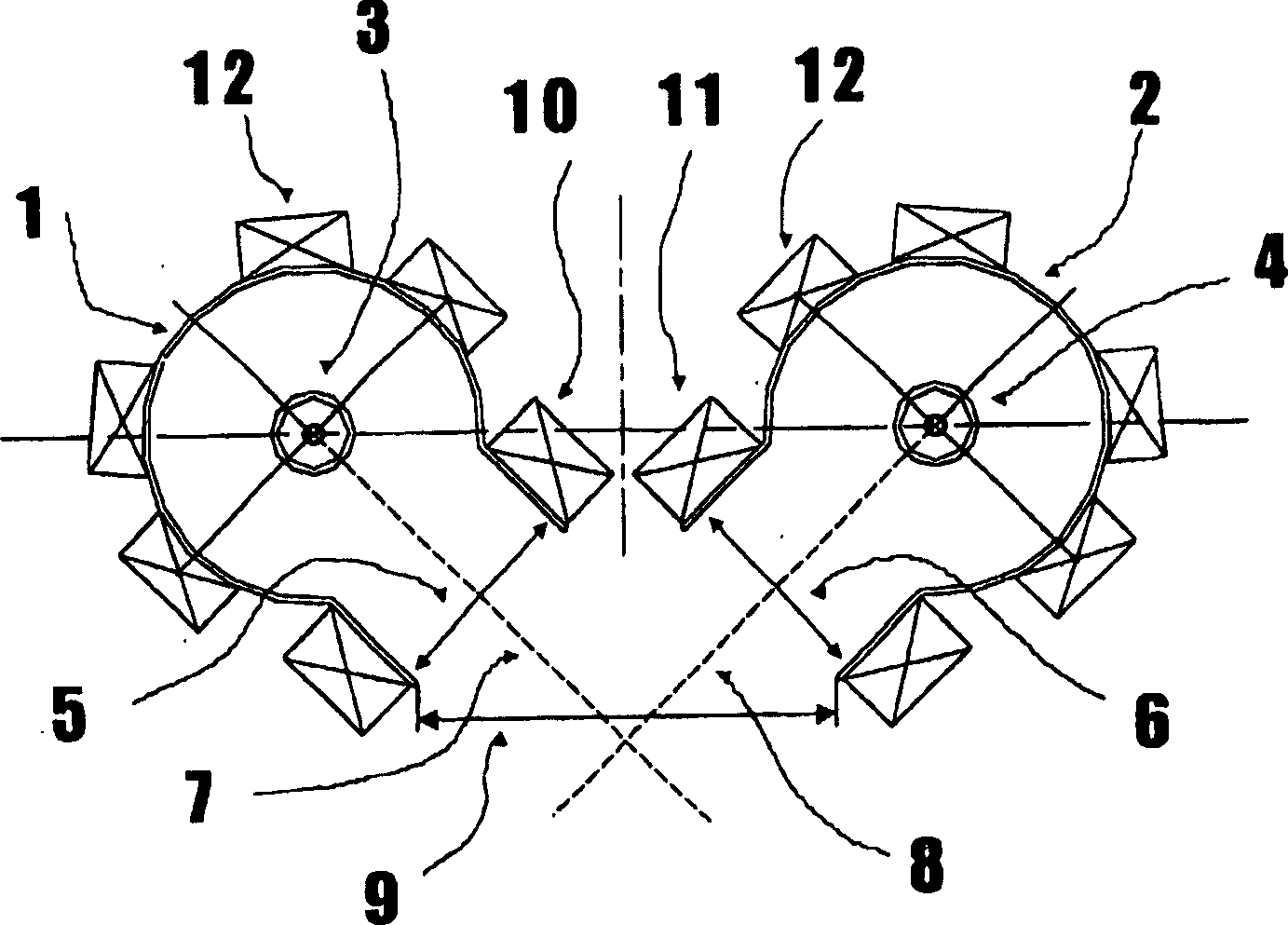
[0021] The ECR plasma source proposed by the present invention according to Embodiment 1 basically consists of two separate ECR plasma sources. figure 1 Two partial plasma chambers 1 and 2 are shown, which together form the plasma chamber of the ECR plasma source and are arranged in a vacuum chamber, not shown in the figure.

[0022] The partial plasma chambers 1 and 2 are of tubular design, within which a separate wave splitter 3 and 4 is respectively arranged coaxially. The wave splitters 3 and 4 correspond to known solutions and comprise an inner conductor which is connected to a device for generating microwaves, in particular in the range between 910 MHz and 2.45 GHz. The wave splitters 3 and 4 are surrounded by protective tubes made of quartz glass. The interior of the protective tube can be flushed with a gas so that the wave distributors 3 and 4 are cooled.

[0023] The walls of the partial plasma chambers 1 and 2 act as outer coaxial waveguides for microwaves and in ...

Embodiment II

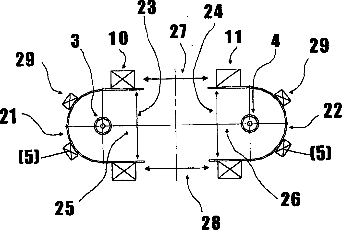
[0030] Belonging to Example II figure 2 An ECR plasma source with two plasma outlets 27 and 28 is schematically depicted in . exist figure 2 The positions consistent with Example 1 are indicated with the same position symbols.

[0031] The two longitudinally extending U-shaped partial plasma chambers 21 and 22 each have a wave splitter 3 and 4 which is arranged in their interior concentrically with the walls of the U-shaped partial plasma chambers 21 and 22, The two partial plasma chambers have partial plasma outlets 23 and 24 over the width of the inner diameter. Wherein, the radial lines 25 and 26 between the width midpoints of the respective wave distributors 3 and 4 and the partial plasma outlets 23 and 24 respectively are on one axis.

[0032]The distance between the partial plasma outlets 23 and 24 is selected such that two oppositely acting linear plasma outlets 27 and 28 are formed at right angles on both sides of the radial lines 25 and 26 . Similar to the situa...

Embodiment III

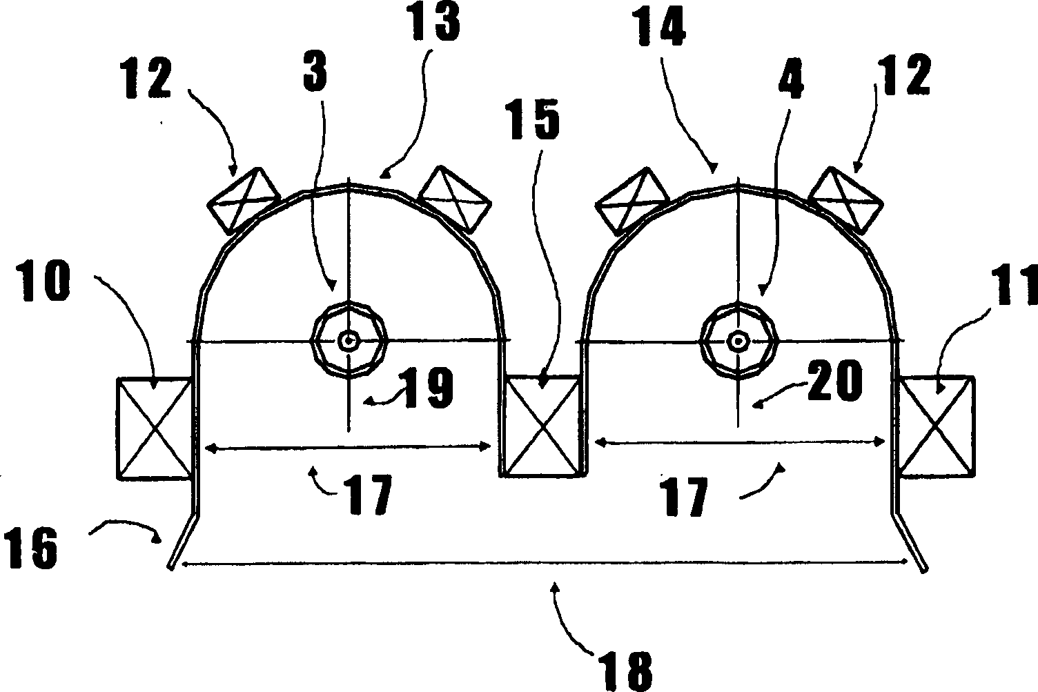
[0035] Belonging to Example III image 3 An ECR plasma source with a plasma outlet 18 is schematically depicted in FIG. exist image 3 The positions consistent with Example 1 are indicated with the same position symbols.

[0036] Two longitudinally extending U-shaped partial plasma chambers 13 and 14 each having a wave splitter 3 and 4 arranged in their interior concentrically with the walls of the U-shaped partial plasma chambers 13 and 14, The two partial plasma chambers each have a partial plasma outlet 17 over the width of the inner diameter. Therein, the radial lines 19 and 20 respectively between the respective wave splitters 3 and 4 and the width midpoint of the partial plasma outlet 17 are parallel to each other and form the plasma outlet 18 of the ECR plasma source.

[0037] Wherein, the U-shaped partial plasma chambers 13 and 14 respectively have an outwardly bent extension 16 on two outer sides of the partial plasma outlet 17, and the length and shape of the exte...


PUM


Abstract

The invention relates to an electron cyclotron resonance (ECR) plasma source having a linear plasma discharge opening ( 9, 27, 28, 30 ), comprised of a plasma chamber, inside of which a centered wave distributor is provided, and having a multi-pole magnetic field arrangement in the area of the linear plasma discharge opening. The centered wave distributor consists of at least two separate wave distributors ( 3, 4 ) that are placed inside a respective partial plasma chamber ( 1, 2, 21, 22, 32, 23 ). A linear partial plasma discharge opening ( 7, 8, 23, 24, 34, 35 ) and multi-pole magnetic field arrangements ( 10, 11, 38, 39 ) are provided on each partial plasma chamber ( 1, 2, 21, 22, 32, 23 ). The at least two linear plasma discharge openings ( 7, 8, 23, 24, 34, 35 ) are arranged with regard to one another in such a manner that, together, they form at least one plasma discharge opening ( 9, 27, 28, 30 ) of the ECR plasma source.

Description

technical field [0001] The present invention relates to an ECR (Electron Cyclotron Resonance) plasma source with a linear plasma outlet on a plasma chamber which at the same time acts as an outer conductor, in which plasma chamber A central wave splitter is connected to a device for generating high frequencies and to a multipole magnetic field device in the region of the linear plasma outlet. All technically applicable and permissible frequency ranges are conceivable as high frequencies. Frequencies between 13.56 MHz and 2.45 GHz have proven to be suitable in practice. Background technique [0002] From the prior art, various plasma generating devices are known. DE 198 12558 A1 describes a kind of ECR ​​plasma ( E lectron- Z yklotron- R esonanz-Plasmen) device. An inner conductor is connected to a device for generating microwaves (910 MHz to 2.45 GHz) and is arranged coaxially in a well-conducting outer coaxial waveguide which simultaneously delimits the plasma chamber...

Claims


Application Information

Patent Timeline
Patent Type & Authority Applications(China)
IPC IPC(8): H01J37/32H05H1/18
CPCH01J37/32192H01J37/32541H01J37/32678H05H1/18
Inventor 约阿希姆·马伊迪特马尔·罗特
Owner ROTH & RAU B V
Why Eureka
Try Eureka