Electron cyclotron resonance (ECR) plasma source having a linear plasma discharge opening
A technology of electron cyclotron resonance and plasma source, which is applied in the direction of plasma, circuit, discharge tube, etc., can solve problems such as fluctuations, and achieve the effect of effective plasma treatment
- Summary
- Abstract
- Description
- Claims
- Application Information
AI Technical Summary
Problems solved by technology
Method used
Image
Examples
Embodiment I
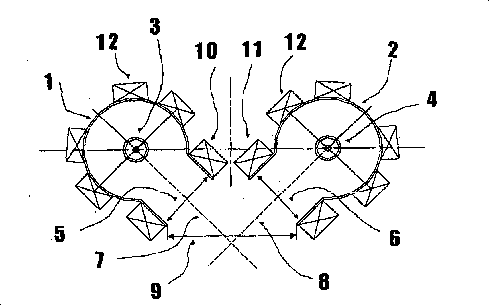
[0021] The electron cyclotron resonance plasma source proposed by the present invention according to Embodiment 1 basically consists of two separate electron cyclotron resonance plasma sources. figure 1 Two partial plasma chambers 1 and 2 are shown, which together form the plasma chamber of the electron cyclotron resonance plasma source and are arranged in a vacuum chamber, not shown in the figure.
[0022] The partial plasma chambers 1 and 2 are of tubular design, within which a separate wave splitter 3 and 4 is respectively arranged coaxially. The wave splitters 3 and 4 correspond to known solutions and comprise an inner conductor which is connected to a device for generating microwaves, in particular in the range between 910 MHz and 2.45 GHz. The wave splitters 3 and 4 are surrounded by protective tubes made of quartz glass. The interior of the protective tube can be flushed with a gas so that the wave distributors 3 and 4 are cooled.
[0023] The walls of the partial pla...
Embodiment II
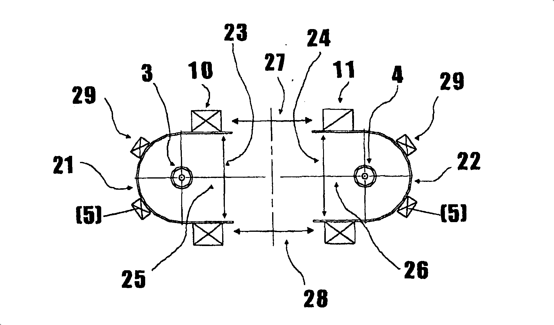
[0030] Belonging to Example II figure 2 An electron cyclotron resonance plasma source with two plasma outlets 27 and 28 is schematically depicted in . exist figure 2 The positions consistent with Example 1 are indicated with the same position symbols.
[0031] The two longitudinally extending U-shaped partial plasma chambers 21 and 22 each have a wave splitter 3 and 4 which is arranged in their interior concentrically with the walls of the U-shaped partial plasma chambers 21 and 22, The two partial plasma chambers have partial plasma outlets 23 and 24 over the width of the inner diameter. Wherein, the radial lines 25 and 26 between the width midpoints of the respective wave distributors 3 and 4 and the partial plasma outlets 23 and 24 respectively are on one axis.
[0032] The distance between the partial plasma outlets 23 and 24 is selected such that two oppositely acting linear plasma outlets 27 and 28 are formed at right angles on both sides of the radial lines 25 and ...
Embodiment III
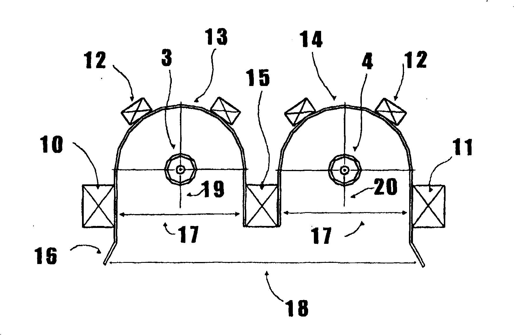
[0035] Belonging to Example III image 3 An electron cyclotron resonance plasma source with a plasma outlet 18 is schematically depicted in . exist image 3 The positions consistent with Example 1 are indicated with the same position symbols.
[0036] Two longitudinally extending U-shaped partial plasma chambers 13 and 14 each having a wave splitter 3 and 4 arranged in their interior concentrically with the walls of the U-shaped partial plasma chambers 13 and 14, The two partial plasma chambers each have a partial plasma outlet 17 over the width of the inner diameter. Therein, the radial lines 19 and 20 between the respective wave splitters 3 and 4 and the width midpoint of the partial plasma outlet 17 are parallel to each other and form the plasma outlet 18 of the electron cyclotron resonance plasma source.
[0037] Wherein, the U-shaped partial plasma chambers 13 and 14 respectively have an outwardly bent extension 16 on two outer sides of the partial plasma outlet 17, an...
PUM
 Abstract
Description
Claims
Application Information
 - R&D
- Intellectual Property
- Life Sciences
- Materials
- Tech Scout
- Unparalleled Data Quality
- Higher Quality Content
- 60% Fewer Hallucinations
Browse by: Latest US Patents, China's latest patents, Technical Efficacy Thesaurus, Application Domain, Technology Topic, Popular Technical Reports.
© 2025 PatSnap. All rights reserved.Legal|Privacy policy|Modern Slavery Act Transparency Statement|Sitemap|About US| Contact US: help@patsnap.com


