
Systems and methods for determining axial orientation and location of a user's wrist

a wrist and axis technology, applied in the field of system and method for determining the axis orientation and location of the user's wrist, can solve the problems of frequent changes in the configuration and/or orientation of the wearable device, inconvenient or impossible for the user to reach into the bag or pocket to find the device, and inability to determine the activity of the user's muscle, etc., to achieve the effect of improving the granularity and/or sensitivity, reducing noise, and reducing the granularity

Active Publication Date: 2018-03-22
APPLE INC
View PDF15 Cites 16 Cited by
  • Summary
  • Abstract
  • Description
  • Claims
  • Application Information

AI Technical Summary

Benefits of technology

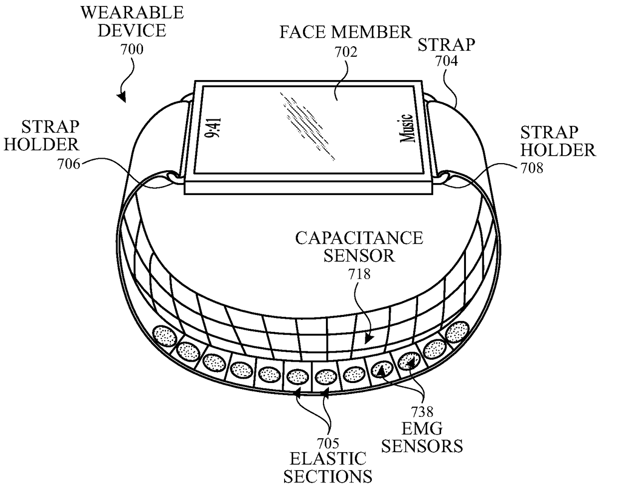
This patent is about a system and method for detecting the orientation and location of a user's wrist using sensors on a strap or device underbody. The strap can have elastic sections and rigid sections, with flex sensors to measure the wrist's expansion or contraction and electromyography sensors to measure muscle activity. The device can also have strain gauges to measure changes in shape, size, and physical properties of the wrist. The system can analyze and provide feedback to the user about their performance, reduce noise, and detect hydration for sensor longevity. The patent allows for increased precision in detecting the user's wrist position.

Problems solved by technology

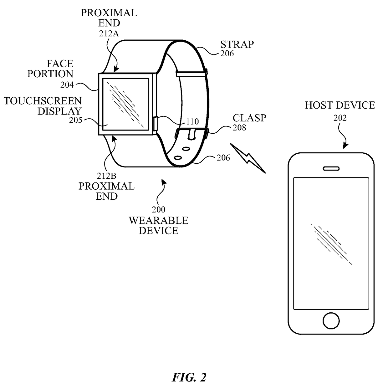
A user's mobile device may not always be readily accessible.
For instance, when a mobile device receives a phone call, the device may be in a user's bag or pocket, and the user may be walking, driving, carrying something, or involved in other activity that can make it inconvenient or impossible for the user to reach into the bag or pocket to find the device.
In some examples, the user's movements can lead to frequent changes in the configuration and / or orientation of the wearable device relative to the user's wrist.

Method used


Image

  • Systems and methods for determining axial orientation and location of a user's wrist
  • Systems and methods for determining axial orientation and location of a user's wrist
  • Systems and methods for determining axial orientation and location of a user's wrist

Examples


Embodiment Construction

[0018]In the following description of examples, reference is made to the accompanying drawings in which it is shown by way of illustration specific examples that can be practiced. It is to be understood that other examples can be used and structural changes can be made without departing from the scope of the various examples.

[0019]Various techniques and process flow steps will be described in detail with reference to examples as illustrated in the accompanying drawings. In the following description, numerous specific details are set forth in order to provide a thorough understanding of one or more aspects and / or features described or referenced herein. It will be apparent, however, to one skilled in the art, that one or more aspects and / or features described or referenced herein may be practiced without some or all of these specific details. In other instances, well-known process steps and / or structures have not been described in detail in order to not obscure some of the aspects an...


PUM

PropertyMeasurementUnit
capacitanceaaaaaaaaaa
tensionaaaaaaaaaa
electrical activitiesaaaaaaaaaa

Abstract

This relates to systems and methods for determining the axial orientation and location of the user's wrist using one or more sensors located on the strap, the device underbody, or both. For example, the strap can include a plurality of elastic sections and a plurality of rigid sections. Each elastic section can include one or more flex sensors. In some examples, on or more electromyography (EMG) sensors can be included to measure the user's electrical signals, and the user's muscle activity can be determined. In some examples, a plurality of strain gauges can be included to generate one or more signals indicative of any changes in shape, size, and / or physical properties of the user's wrist. In some examples, the device can include a plurality of capacitance sensors for increased granularity and / or sensitivity in measuring the amount of tension exerted by the user's wrist.

Description

CROSS REFERENCE TO RELATED APPLICATIONS[0001]This application claims the benefit under 35 USC 119(e) of U.S. Patent Application No. 62 / 398,338, filed Sep. 22, 2016, the contents of which are incorporated herein by reference in their entirety for all purposes.FIELD OF THE DISCLOSURE[0002]This relates to systems and method for determining axial orientation and location of a user's wrist.BACKGROUND OF THE DISCLOSURE[0003]Mobile electronic devices, such as mobile phones, smart phones, table computers, media players, and the like, have become quite popular. Many users carry a device almost everywhere they go and use their devices for a variety of purposes, including making and receiving phone calls, sending and receiving text messages and emails, navigation (e.g., using maps and / or a GPS receiver), purchasing items in a store (e.g., using contactless payment systems), and / or accessing the Internet (e.g., to look up information).[0004]A user's mobile device may not always be readily acces...

Claims


Application Information

Patent Timeline
Patent Type & Authority Applications(United States)
IPC IPC(8): A61B5/11A61B5/00A61B5/0492A61B5/024A63B24/00A63B71/06G01L1/14G01L1/16A61B5/296
CPCA61B5/1122A61B5/681A61B5/0492A61B5/02416A63B24/0062A63B24/0006A63B71/0619G01L1/146G01L1/16A61B2562/0214A61B5/1112A61B5/067A61B5/486A63B2220/50A63B2220/40A63B2024/0012A63B2220/803A63B2220/836A63B2230/08A63B2071/0663G01P13/00G06F3/044G06F3/017G06F3/011A61B5/6886A61B5/1118A61B5/224A63B2230/60G06F1/163A61B5/296
Inventor LOR, JASONNANGIA, SIDDHARTH
Owner APPLE INC
Learn More