Implant and method for long bone fixation

a long bone and implant technology, applied in the field of implants and methods for long bone fixation, can solve the problems of increasing the risk of tendon adhesion of plates in these bones, relatively invasive methods, and increasing the risk of plates having issues with tendon adhesion, so as to improve bone fixation and increase the profile

Active Publication Date: 2018-03-22
MEDULOC LLC
View PDF52 Cites 6 Cited by
  • Summary
  • Abstract
  • Description
  • Claims
  • Application Information

AI Technical Summary

Benefits of technology

[0013]Optionally, in any embodiment, the distal tip of the fixation implant may expand into an arcuate shape having an increased profile for anchoring the distal tip in the long bone. The arcuate shape may be any shape including but not limited to a ring, an undulating shape, a J-shape, or a Shepherd's crook. The distal tip may have one or more grooves for improved bone fixation.

Problems solved by technology

Such a method is relatively invasive when compared to other common methods due to large soft tissue dissection needed for plate placement.
Plates can handle difficult fracture patterns; however, proper alignment and repair with this method is strongly dependent on fracture type and physician skill set.
Plates have additional issues in smaller bones such as the metacarpals.
Plates in these bones are more likely to have issues with tendon adhesion due to the raised surface of the plate, prevalence of tendons, and the tight anatomy which may cause range of motion issues in the hand after surgery.
This method also creates a larger scar than other methods.
Although this method is less invasive than plates, it is only able to be done on spiral and oblique fractures and is a technically difficult procedure.
Some of the challenges associated with conventional intramedullary fixation methods include lack of rotational stability and / or undesired migration of nails and wires.
Intramedullary fixation methods may also introduce interlocking screws across the nail for larger bones, creating some disadvantages.
This step greatly increases the complexity of the surgery and requires extra incisions, and requires additional X-rays.

Method used


Image

  • Implant and method for long bone fixation
  • Implant and method for long bone fixation
  • Implant and method for long bone fixation

Examples


Embodiment Construction

[0095]Specific embodiments of the disclosed device and method of use will now be described with reference to the drawings. Nothing in this detailed description is intended to imply that any particular component, feature, or step is essential to the invention.

[0096]It would be desirable to provide improved fracture fixation devices and methods that overcome some of the challenges of existing treatments. For example, it would be desirable to provide an intramedullary device that provides both rotational and longitudinal stability to a fractured bone. Additionally, it would be desirable to provide an intramedullary device that provides rotational stability without the addition of perpendicular screws. The embodiments described herein address at least some of these challenges.

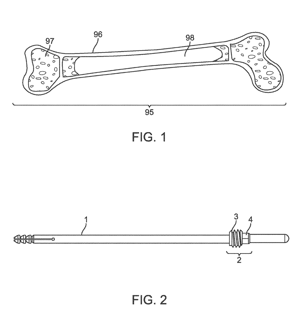
[0097]FIG. 1 shows an embodiment of a long bone 95. FIG. 1 illustrates an embodiment with optional features, any of which may be optionally used or substituted with other features in other embodiments discussed her...


PUM


Abstract

An implant and method for fixation of long bones. The implant provides rotational, longitudinal, and bending stability. The implant comprises one or more elongated members that span the intramedullary cavity of a long bone, a distal tip that expands radially relative to the long axis of the implant, and a locking mechanism at the proximal end of the implant.

Description

CROSS-REFERENCE TO RELATED APPLICATIONS[0001]The present application is a non-provisional of, and claims the benefit of US Provisional Patent Application Nos. 62 / 385,044 (Attorney Docket No. 44057-714.101) filed Sep. 8, 2016, and 62 / 450,700 (Attorney Docket No. 44057-714.102) filed Jan. 26, 2017; the entire contents of which are incorporated herein by reference in their entirety.BACKGROUND OF THE INVENTION[0002]Fractures of long bones are currently treated with a variety of internal fixation devices, including plates which are fixated to the surface of a bone with screws, nails or wires running inside the medullary canal, and / or screws affixing both ends of a fractured bone together. In general, fracture fixation using methods listed above or others may provide longitudinal (along the long axis of the bone), transverse (across the long axis of the bone), and rotational (about the long axis of the bone) stability. Fracture fixation may also preserve normal function during and after h...

Claims


Application Information

Patent Timeline
Patent Type & Authority Applications(United States)
IPC IPC(8): A61B17/72
CPCA61B17/7266A61B17/1604A61B17/1717A61B17/7225A61B17/7233A61B17/7275A61B17/7291A61B17/80A61B17/8863A61B17/8872A61B17/8875A61B17/921
Inventor HUSTEDT, JOSHUAARNOLD, BENJAMINBOWMAN, BRIANPENA, KRISTEN
Owner MEDULOC LLC
Why Eureka
Try Eureka