
A support assembly for movable shaft in particular for machinery for the food industry

a technology for supporting assemblies and machinery, applied in the direction of shafts and bearings, rotary bearings, bearings, etc., can solve the problems of not being able to obtain valid certifications, dirt can stagnate, and the lid cannot meet the outer surface of the housing, so as to achieve high ease of assembly and disassembly.

Active Publication Date: 2018-03-22
AB SKF
View PDF0 Cites 2 Cited by
  • Summary
  • Abstract
  • Description
  • Claims
  • Application Information

AI Technical Summary

Benefits of technology

The present invention aims to provide a support assembly for furniture trees that can be mounted on machines for the food industry without any gaps where water, moisture, and dirt can accumulate. Furthermore, it should be easy to assemble and disassemble without tools and minimize the risk of damage or loosening of the coupling cover / housing element as a result of frequent disassembly.

Problems solved by technology

This problem is particularly felt with respect to the complex support of mobile trees, which may be either type of terminal, where is housed a terminal end of the shaft, or feed through type.
Moreover, it can remain even in this case, however, a gap between the lid and outer surface of the housing, due to the type of mechanical coupling used.
The creation of these interstices between the housing and the cover element, the interstices in which water and dirt can stagnate, however, is entirely undesirable and does not allow to obtain valid certifications for the food industry.
Finally, the assembly of the kind described have the further drawback of being able to cause, as a result of repeated assembly and disassembly, damage to the cover and / or the creation of games, that loosen the coupling (so much so that in some cases the cover may accidentally come off) and / or that aggravate the formation of interstices where water, moisture and dirt can stagnate.

Method used


Image

  • A support assembly for movable shaft in particular for machinery for the food industry
  • A support assembly for movable shaft in particular for machinery for the food industry
  • A support assembly for movable shaft in particular for machinery for the food industry

Examples


Embodiment Construction

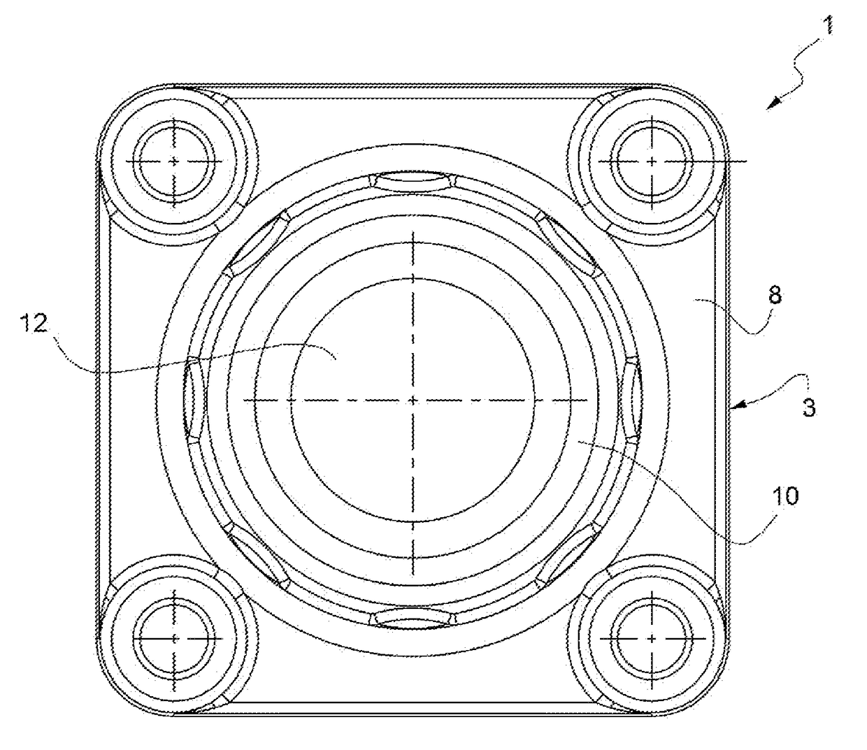
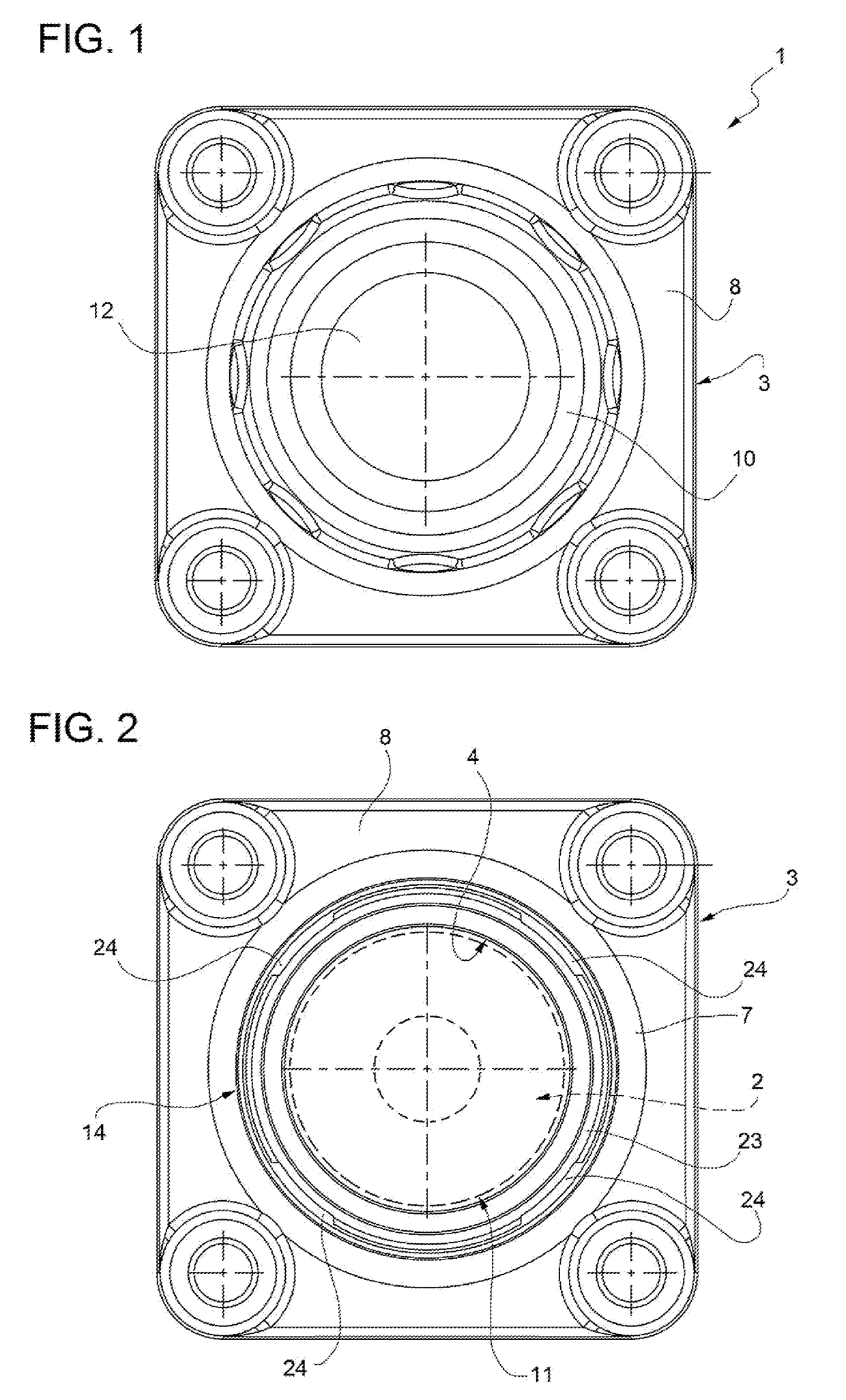
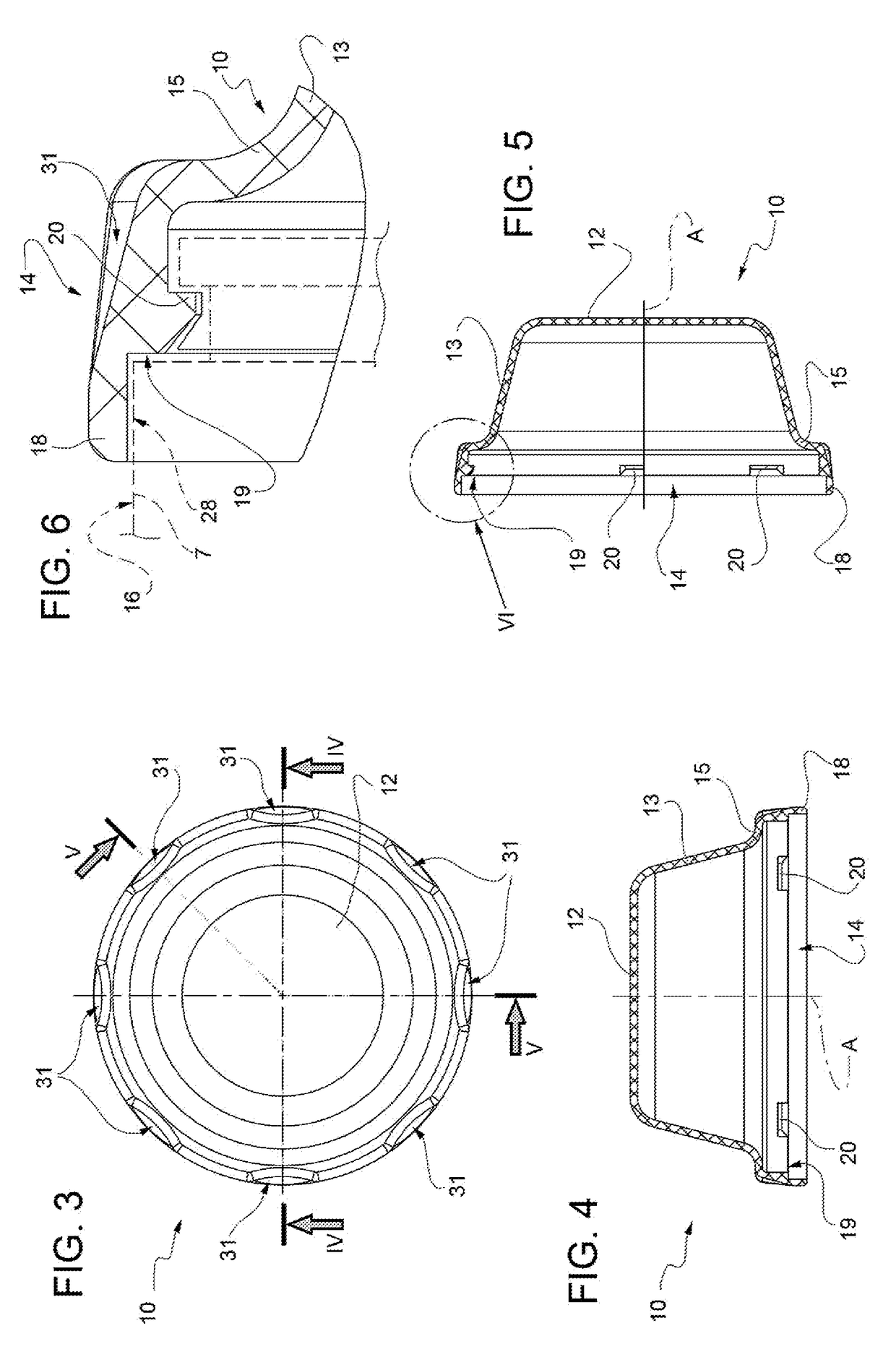
[0019]With reference to FIGS. 1 to 7, number 1 indicates as a whole a support assembly for movable shafts, rotating or sliding, not illustrated for simplicity.

[0020]The support assembly 1 comprises a bearing 2 (FIG. 2), for example a rolling bearing, known and only shown schematically in broken lines for simplicity, adapted to receive in a movable shaft known manner, for example rotating, to support it, and a of the bearing housing 3 having a through seat 4 within which is received the bearing 2 in a stable and known manner, therefore not illustrated for simplicity.

[0021]The support assembly 1 is in particular intended to be mounted on machines for the food industry. For this purpose, the bearing housing 3, which is illustrated in perspective view in FIG. 7, is of the type intended to be rigidly mounted on a machine frame of a known type, not illustrated for simplicity, in particular for the food industry.

[0022]The bearing housing 3 comprises a housing element 7, in the annular comp...


PUM


Abstract

A supporting assembly including a bearing, a bearing housing having an annular element housing and a base for fixing, and a cover for close fluid tight an opening of the housing element; the cover being cup-shaped and including an annular coupling portion to a radially outer lateral surface for housing the annular element. The coupling portion provided radially on the inside with at least a pair of teeth projecting radially towards the inside of the lid; the lateral surface of the annular element housing provided with an annular seat for the teeth of the lid, including: an annular groove disposed axially spaced with respect to a front edge of the housing element; axial grooves equal to the number of teeth present and that radially interrupt the front edge; and a bottom wall provided with a plurality of alternating troughs and projections arranged offset circumferentially with respect to the axial grooves.

Description

TECHNICAL FIELD OF THE INVENTION[0001]The present invention relates to a support assembly for furniture trees, for example rotating, in particular intended to be mounted on machines for the food industry.KNOWN ART[0002]As it is known, the machines used in the food industry have many moving parts supported by sliding or rotating shafts, think for example conveyor belts, kneading machines, machines for washing of fresh food.[0003]All these machines must be cleaned frequently, usually with water added with detergent and or disinfectants, in order to monitor the possible occurrence of bacterial colonies which may pollute foods. In particular, it is necessary that these machines do not exhibit interstices or other parts where dirt, or even only the washing water, can penetrate and stagnate. The stagnation of liquids or moisture favors in fact a possible proliferation of bacteria.[0004]This problem is particularly felt with respect to the complex support of mobile trees, which may be eith...

Claims


Application Information

Patent Timeline
Patent Type & Authority Applications(United States)
IPC IPC(8): F16C33/72F16C17/02F16C35/02
CPCF16C33/723F16C17/02F16C35/02F16C35/00
Inventor FALASCHI, FABIOBARACCA, FAUSTO
Owner AB SKF
Learn More