Actuator

Inactive Publication Date: 2018-03-22
JOHNSON ELECTRIC INTERNATIONAL AG
View PDF9 Cites 10 Cited by
  • Summary
  • Abstract
  • Description
  • Claims
  • Application Information

AI Technical Summary

Benefits of technology

The invention aims to solve issues by eliminating a separation plate in an actuator, resulting in a more compact actuator arrangement.

Problems solved by technology

The separation plate increases the overall bulk of the actuator, since it fills valuable internal space inside the actuator housing, and also increases the complexity of assembly of the actuator, as a greater number of components must be interengaged.

Method used


Image

  • Actuator
  • Actuator
  • Actuator

Examples


Embodiment Construction

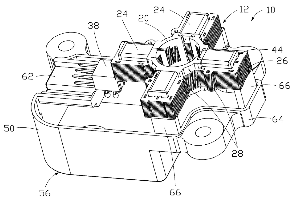
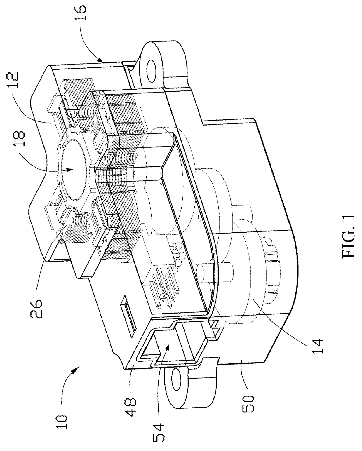
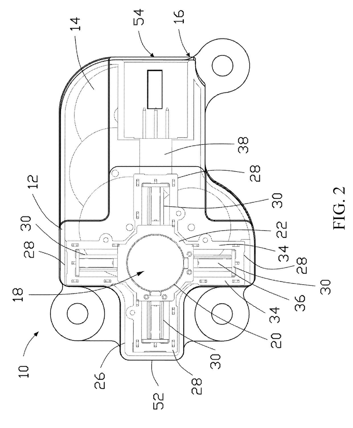
[0026]Referring to FIGS. 1 to 3, there is provided an actuator, indicated globally at 10, which is preferably provided as a stepper actuator suitable for use in an automotive context, for example, as part of a heating, ventilation and air conditioning (HVAC) system.

[0027]The stepper actuator 10 comprises an electric motor 12 and a gear train 14 which are enclosed within an actuator housing 16. In the present arrangement, at least some of the individual gears of the gear train 14 are oriented such that their footprint overlaps with that of the electric motor 12 when installed into the actuator housing 16.

[0028]The electric motor 12 is here formed as a star motor having a central rotor 18 and a stator 26 mounted around the rotor 18. The stator 26 includes a bobbin 22, plurality of stator windings 24, and a plurality of core lamination units 28. The bobbin 22 includes a receiving portion 20, in which the rotor 18 is rotatably received, and a plurality of winding supporting portions 30 ...


PUM


Abstract

An actuator includes an electric motor and an actuator housing accommodating the electric motor. The electric motor includes a stator and a rotor. The stator includes: a bobbin having a rotor receiving portion rotatably receiving the rotor, and a plurality of winding supporting portions extending from the rotor receiving portion; a plurality of stator winding respectively mounted on the winding supporting portions; and a plurality of core lamination units engagable with the winding supporting portions. The actuator housing includes a plurality of motor supports integrally formed in the actuator housing. The motor supports directly engaged the stator to support the electric motor inside the actuator housing.

Description

CROSS REFERENCE TO RELATED APPLICATIONS[0001]This non-provisional patent application claims priority under 35 U.S.C. § 119(a) from Patent Application No. 1615968.3 filed in United Kingdom on Sep. 20, 2016.FIELD OF THE INVENTION[0002]The present invention relates to an actuator, preferably but not necessarily exclusively a stepper actuator for use in automotive contexts.BACKGROUND OF THE INVENTION[0003]One of the most important features of an electric actuator, particularly in automotive contexts, is its overall size, be its volume or the footprint of the actuator in two dimensions. Where footprint is the more critical variable, often the internal components of the electric actuator can be stacked in a vertical direction in order to ensure optimum overlap between the components, typically by stacking the electric motor and the gear train.[0004]Typically, a cylindrical stepper motor is provided in an actuator, and this requires a set amount of space upon which it can be securely seate...

Claims


Application Information

Patent Timeline
IPC IPC(8): F16K31/04
CPCF16K31/047H02K5/15H02K5/225H02K7/116H02K11/21B60H1/00857H02K3/50H02K5/04H02K37/24H02K1/14H02K1/185H02K3/521H02K3/46H02K3/524H02K7/14
Inventor BOURQUI, YVAN
Owner JOHNSON ELECTRIC INTERNATIONAL AG
Why Eureka
Try Eureka