
Methods Circuits Devices Assemblies Systems and Functionally Associated Machine Executable Code for Light Detection and Ranging Based Scanning

a technology of circuit devices and assemblies, applied in the field of light detection and ranging, can solve the problems of unsuitable mass market, unreliable, high cost of lidar systems, drones, etc., and achieve the effect of reducing the reception field of view and increasing the transmission beam spread

Inactive Publication Date: 2018-03-22
INNOVIZ TECH LTD
View PDF1 Cites 66 Cited by
  • Summary
  • Abstract
  • Description
  • Claims
  • Application Information

AI Technical Summary

Benefits of technology

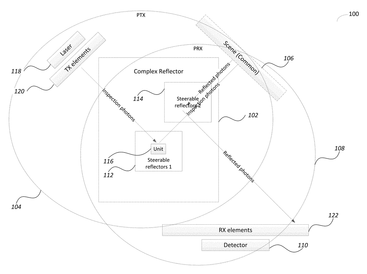
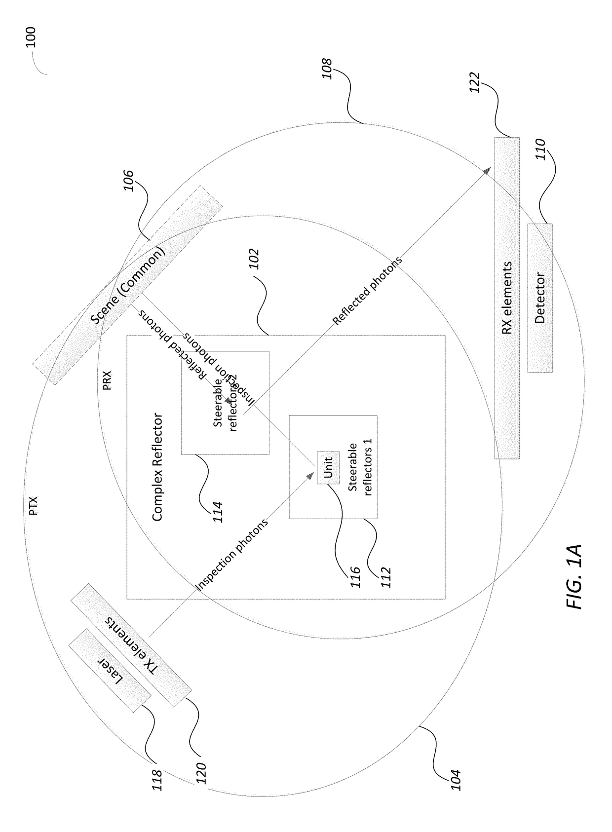
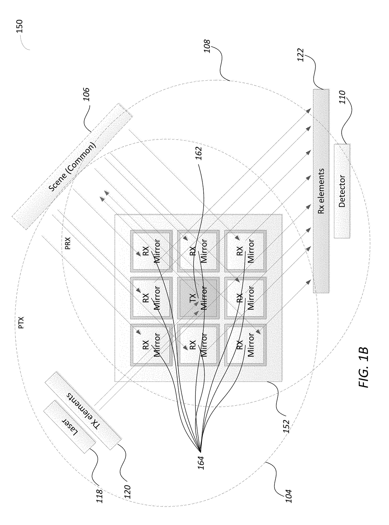
The patent describes a system with two sets of stearable reflectors that can be controlled to steer a laser beam in different directions. The first set of reflectors can be synchronized with each other and the second set can also be synchronized. The two sets of reflectors can also oscillate at different frequencies, which can create a fixed phase shift. The system can adjust the number of reflectors in either the transmission or reception state to control the beam spread and compensate for ambient light conditions. When the reflectors are not in use, they provide isolation between them. Overall, the system allows for highly precise and efficient beam steering in various applications such as laser scanning and optical imaging.

Problems solved by technology

Lidar systems, drones and autonomous (or semi-autonomous) vehicles are currently expensive and non-reliable, unsuitable for a mass market where reliability and dependence are a concern—such as the automotive market.

Method used


Image

  • Methods Circuits Devices Assemblies Systems and Functionally Associated Machine Executable Code for Light Detection and Ranging Based Scanning
  • Methods Circuits Devices Assemblies Systems and Functionally Associated Machine Executable Code for Light Detection and Ranging Based Scanning
  • Methods Circuits Devices Assemblies Systems and Functionally Associated Machine Executable Code for Light Detection and Ranging Based Scanning

Examples


Embodiment Construction

[0028]In the following detailed description, numerous specific details are set forth in order to provide a thorough understanding of the invention. However, it will be understood by those skilled in the art that the present invention may be practiced without these specific details. In other instances, well-known methods, procedures, components and circuits have not been described in detail so as not to obscure the present invention.

[0029]Unless specifically stated otherwise, as apparent from the following discussions, it is appreciated that throughout the specification discussions utilizing terms such as “processing”, “computing”, “calculating”, “determining”, or the like, refer to the action and / or processes of a computer or computing system, or similar electronic computing device, that manipulate and / or transform data represented as physical, such as electronic, quantities within the computing system's registers and / or memories into other data similarly represented as physical qua...


PUM


Abstract

Disclosed is a light detection and ranging (Lidar) device including a photonic pulse emitter assembly including one or more photonic emitters to generate and focus a photonic inspection pulse towards a photonic transmission (TX) path of the Lidar device, a photonic detection assembly including one or more photo sensors to receive and sense photons of a reflected photonic inspection pulses received through a receive (RX) path of the device, a photonic steering assembly located along both the TX and the RX paths and including a Complex Reflector (CR) made of an array of steerable reflectors, where a first set of steerable reflectors are part of the TX path and a second set of steerable reflectors are part of the RX path.

Description

RELATED APPLICATIONS[0001]The present application claims priority from U.S. Provisional Patent Application No. 62 / 397,379, entitled: “Array of piezoelectric MEMS mirrors for Lidar applications”, filed on Sep. 21, 2016 which is hereby incorporated by reference into the present application in its entiretyFIELD OF THE INVENTION[0002]The present invention relates generally to the field of light detection and ranging. More specifically, the present invention relates to a Lidar with a photonic steering assembly.BACKGROUND[0003]Lidar which may also be called “LADAR” is a surveying method that measures a distance to a target by illuminating that target with a laser light. Lidar is sometimes considered an acronym of “Light Detection and Ranging”, or a portmanteau of light and radar. Lidar may be used with terrestrial, airborne, and mobile applications.[0004]Autonomous Vehicle Systems are directed to vehicle level autonomous systems involving a Lidar system. An autonomous vehicle system stand...

Claims


Application Information

Patent Timeline
Patent Type & Authority Applications(United States)
IPC IPC(8): G01S7/481G01S17/08
CPCG01S17/08G01S7/4817G01S17/10G01S17/42G01S7/4815
Inventor MEDINA, MOSHEDAVID, SMADARVLAIKO, JULIANELOOZ, DAVIDANTMAN, YAIRBUSKILA, OREN
Owner INNOVIZ TECH LTD
Learn More