Method For Controlling A Fuel Delivery System

a fuel delivery system and fuel injection technology, applied in the direction of electric control, fuel injection control, machines/engines, etc., can solve the problem of increasing the pressure in the fuel delivery system, and achieve the effect of improving the control of the fuel delivery system and broadening the operating rang

Active Publication Date: 2018-03-29
VITESCO TECH GERMANY GMBH
View PDF3 Cites 0 Cited by
  • Summary
  • Abstract
  • Description
  • Claims
  • Application Information

AI Technical Summary

Benefits of technology

[0009]It is therefore an aspect of the present invention is to provide a method that provides an improved control of the fuel delivery system and, in particular, of the fuel delivery pump possible, no pressure sensor being used in the fuel delivery system. Furthermore, an aspect of the invention is to provide a method that can be applied to as great a multiplicity as possible of different fuel delivery systems and to as broad an operating range as possible of fuel delivery systems.
[0012]The pressure loss can be compensated for by way of an increase in the pump rotational speed, since the fuel delivery quantity is increased by way of the increase in the pump rotational speed and the pressure rises slightly at the same time, as a result of which the additional hydraulic losses can be compensated for.
[0019]This is particularly advantageous, since, starting from the pressure level at the calibration point, there is a known dependence that is specific for the respective fuel delivery system between the fuel delivery quantity and the pressure in the fuel delivery system. In addition, the respective consumption quantity of the fuel is to be taken into consideration, which consumption quantity consists of the fuel requirement of the internal combustion engine and the fuel quantity which is possibly required for the operation of suction jet pumps. The fuel delivery quantity which is required for the operation of suction jet pumps is as a rule considerably lower than the fuel requirement of the internal combustion engine, with the result that a very accurate result is achieved in a first approximation, even if the fuel quantity required for the operation of the suction jet pump is disregarded.
[0021]A characteristic diagram of this type or a plurality of characteristic diagrams of this type can be determined in a simple way by way of empirical tests or by way of a calculation for a respectively known fuel delivery system. The characteristic diagrams can be stored in the control units used for controlling and regulating the fuel delivery system. In this way, a very accurate determination of the pressure in the fuel delivery system can be achieved using simple means.
[0022]Moreover, it is advantageous if the curves of the characteristic diagram which is used to determine the pressure in the fuel delivery system form a straight line with a high ascending gradient for each fuel requirement of the internal combustion engine within a defined pressure range.
[0026]Moreover, it is advantageous if a value for the fuel requirement of the internal combustion engine is provided by a control unit of the internal combustion engine. In modern fuel injection systems and internal combustion engines, the respectively required fuel and the consumed fuel are as a rule known very accurately on account of the complexity of the combustion. The value for the fuel requirement can therefore be provided at a high quality without additional complexity by one of the control units that controls the combustion in the internal combustion engine.

Problems solved by technology

As a result, the pressure in the fuel delivery system rises somewhat, since an additional pressure loss is produced by way of the suction jet pump and other possibly present consumers.

Method used


Image

  • Method For Controlling A Fuel Delivery System
  • Method For Controlling A Fuel Delivery System
  • Method For Controlling A Fuel Delivery System

Examples


Embodiment Construction

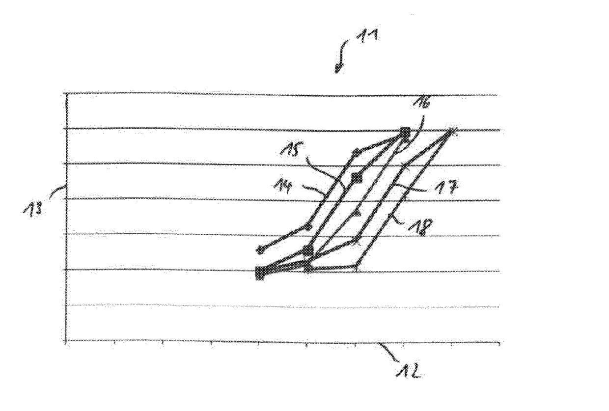
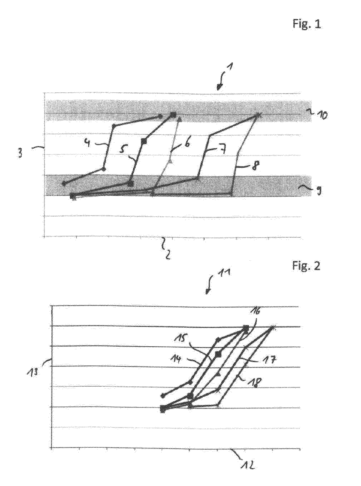
[0033]FIG. 1 shows a graph 1. In the graph 1, the fuel delivery quantity of a fuel delivery pump in a fuel delivery system is plotted on the X-axis 2. Here, the fuel delivery quantity is plotted for a range from zero liters per hour at the point of intersection with the Y-axis 3 up to 80 liters per hour on the right-hand end region of the X-axis 2. The pressure that prevails in the fuel delivery system is plotted on the Y-axis 3. The curves 4, 5, 6, 7, and 8 represent the respective fuel requirement of an internal combustion engine. The curve 4 corresponds to a fuel requirement of 20 liters per hour, the curve 5 corresponds to a fuel requirement of 30 liters per hour, the curve 6 corresponds to a fuel requirement of 40 liters per hour, the curve 7 corresponds to a fuel requirement of 50 liters per hour, and the curve 8 corresponds to a fuel requirement of 60 liters per hour. The fuel requirements of the graph 1 are by way of example and represent values for a specific fuel delivery ...


PUM


Abstract

A method for controlling a fuel delivery system of an internal combustion engine, having a fuel delivery pump that is driven by an electric motor. The pressure that prevails in the fuel delivery system is determined by a volume difference between the fuel quantity delivered by the fuel delivery pump and the fuel requirement of the internal combustion engine and / or of the fuel delivery system.

Description

CROSS REFERENCE TO RELATED APPLICATIONS[0001]This is a U.S. national stage of application No. PCT / EP2016 / 059159, filed on Apr. 25, 2016. Priority is claimed on German Application No. DE102015207700.4, filed Apr. 27, 2015, the content of which is incorporated here by reference.BACKGROUND OF THE INVENTION1. Field of the Invention[0002]The invention relates to a method for controlling a fuel delivery system of an internal combustion engine, having a fuel delivery pump driven by electric motor.2. Description of the Prior Art[0003]Fuel delivery pumps are used in fuel delivery systems of motor vehicles to meet the fuel requirement of the internal combustion engine. In addition, the operation of additional assemblies, such as suction jet pumps, is made possible by the fuel delivered by way of the fuel delivery pump.[0004]In order to make a precise control of the fuel delivery pump possible, the pressure in the fuel delivery system is required as a relevant variable. The determination of th...

Claims


Application Information

Patent Timeline
Patent Type & Authority Applications(United States)
IPC IPC(8): F02D1/02
CPCF02D1/02F02D2200/0602F02D41/3082F02D2200/0604F02D2200/0614F02D41/2432F02D41/3854F02D41/3836
Inventor BEHRENDT, GERALD
Owner VITESCO TECH GERMANY GMBH
Why Eureka
Try Eureka