Fractal fluid passages apparatus

a fluid passage and fluid passage technology, applied in the field of structures, can solve the problems of limited design and manufacturing methods, and achieve the effect of decreasing the cross-sectional area

Inactive Publication Date: 2018-03-29
ADDITIVE ROCKET CORP
View PDF4 Cites 14 Cited by
  • Summary
  • Abstract
  • Description
  • Claims
  • Application Information

AI Technical Summary

Benefits of technology

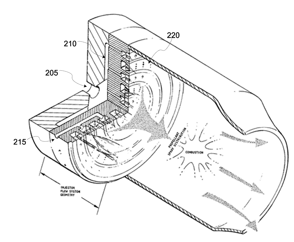
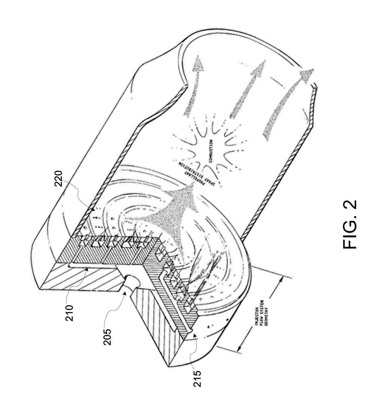
[0023]In some embodiments another apparatus is presented that includes: a plurality of fractal fluid passages including: an inlet; a fluid diverter coupled to the inlet and comprising an annulus with progressively decreasing cross-sectional area; a first fractal fluid branching passage coupled to the fluid diverter; a second fractal fluid branching passage coupled to the fluid diverter and having an equal cross-sectional area to the first fractal fluid branching passage; a third fractal fluid branching passage and a fourth fractal fluid branching passage, the third and fourth fractal fluid branching passages coupled to the first fractal fluid branching passage with continuously smooth curvature to the first fractal fluid branching passage such that the fluid flowing from the first fractal fluid branching passage is configured to flow into both the third and fourth fractal fluid branching passages with minimal change in pressure drop; and a fifth fractal fluid branching passage and a sixth fractal fluid branching passage, the fifth and sixth fractal fluid branching passages coupled to the second fractal fluid branching passage with continuously smooth curvature to the second fractal fluid branching passage such that the fluid flowing from the second fractal fluid branching passage is configured to flow into both the fifth and sixth fractal fluid branching passages with minimal change in pressure drop.

Problems solved by technology

These designs are therefore limited by the manufacturing methods employed.

Method used


Image

  • Fractal fluid passages apparatus
  • Fractal fluid passages apparatus
  • Fractal fluid passages apparatus

Examples


Embodiment Construction

[0048]Building fluid passages in an apparatus tends to rely on traditional, subtractive, manufacturing methods for their production. As a result, their designs reflect the limitations of the manufacturing methods employed. The passages, for example, built in engines or other large machines are typically created in more than one piece, and are welded or fastened together, using o-rings or other gaskets to seal high pressure regions. These designs exhibit numerous failure points. The designs for fluid passages can be improved to reduce stress points and create more even flow throughout.

[0049]Producing an apparatus possessing one or more series of fluid passages through additive manufacturing (AM) offers a multitude of previously unseen improvements. The ability to print a these passages in a single piece using AM techniques increases durability and usability while reducing weight. The speed at which additive manufacturing methods are able to produce components outpaces even the most a...


PUM

PropertyMeasurementUnit
pressure dropaaaaaaaaaa
injection angleaaaaaaaaaa
pressure dropaaaaaaaaaa

Abstract

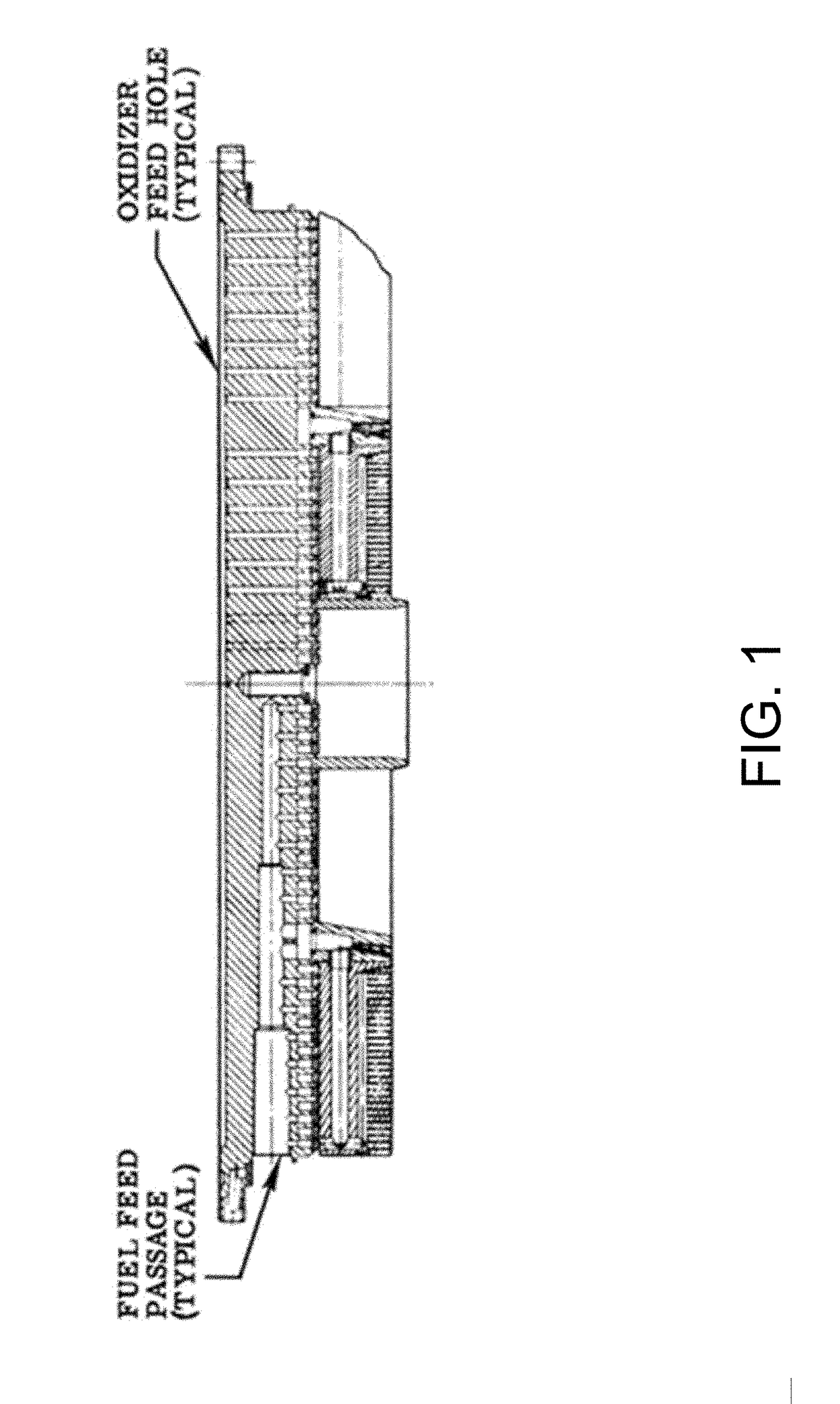
Aspects of the present disclosure include branching fluid passages in an apparatus that reduce turbulent flow and generate evenly distributed fluid pressure as the fluids branch off into the different passages. In some embodiments, the branching passages may be subdivided into two sets: the branching passages for the liquid fuel and the branching passages for the liquid oxidizer. In some embodiments, the two sets of passages are carefully designed in an elegant yet extremely intricate manner that is optimized for proper fluid flow and maximal burn efficiency. The ends of all of the passages meet at the injector interface, which dispense the liquids into the combustion chamber for ignition. Generally, these designs are achieved through additive manufacturing, and would be extremely difficult, if not impossible, to be manufactured using traditional techniques.

Description

CROSS REFERENCE TO RELATED APPLICATION[0001]This application claims the benefit of U.S. Provisional Application 62 / 385,122, filed Sep. 8, 2016, and titled “FRACTAL FLUID PASSAGES APPARATUS,” the disclosure of which is hereby incorporated herein in its entirety and for all purposes.TECHNICAL FIELD[0002]The subject matter disclosed herein generally relates to structures for injecting, distributing, and / or mixing. More specifically, the present disclosures relate to fractal fluid passages in apparatuses with various industrial applicability.BACKGROUND[0003]Conventionally, channels for allowing the flow of fluid are manufactured using subtractive manufacturing methods, meaning that larger pieces of material are used which are whittled down and bored through until a desired structure is created. These designs are therefore limited by the manufacturing methods employed. In addition, structures with fluid passages are conventionally built with multiple pieces, needing to be welded and fast...

Claims


Application Information

Patent Timeline
Patent Type & Authority Applications(United States)
IPC IPC(8): F16L41/03F02M61/16B33Y80/00
CPCF16L41/03F02M61/16B33Y80/00F02M61/1806Y10T137/85938F02M35/10347F02K9/52F01D5/186B29C64/00F05D2230/30F02K9/972F02K9/64F23D14/22F16L41/023B29C45/2725B01J19/2485G01N30/6017F23R3/28B01J2219/247B01L2300/0864B01L2300/0874F16L41/02
Inventor ADRIANY, KYLEBAYAT, ELYCEGARRETT, NICHOLASPEDERSEN, RYANWEEKES, REILEYTRAN, ANTHONY
Owner ADDITIVE ROCKET CORP
Why Eureka
Try Eureka