Display system and components

a technology of display system and components, applied in the field of display system, can solve the problems of projectors of this type with a relatively high life cycle cost compared to other types of displays, loss of intensity of light, and complicated optical problems associated with them

Inactive Publication Date: 2018-03-29
L 3 COMM CORP
View PDF4 Cites 8 Cited by
  • Summary
  • Abstract
  • Description
  • Claims
  • Application Information

AI Technical Summary

Benefits of technology

[0009]According to another aspect of the invention, a component for a display system comprises a faceplate comprising a number of optical fibers secured therein. Each of the fibers has a first end supported in a planar surface of the faceplate and a second end opposite to the first end supported in a concave spherical surface of the faceplate. The first end is configured so as to receive light from an image engine associated with the faceplate, and the second end is configured so as to transmit the light from the first end...

Problems solved by technology

Unfortunately, projectors of this type have a relatively high life cycle cost compared to other types of display.
Some issues associated with binocular perspective viewing can cause operational problems when the trainee is viewing the OTW scenery on the screen and also using imagery or symbology on a helmet-mounted display, due to the difference in distance from the traine...

Method used


Image

  • Display system and components
  • Display system and components
  • Display system and components

Examples


Embodiment Construction

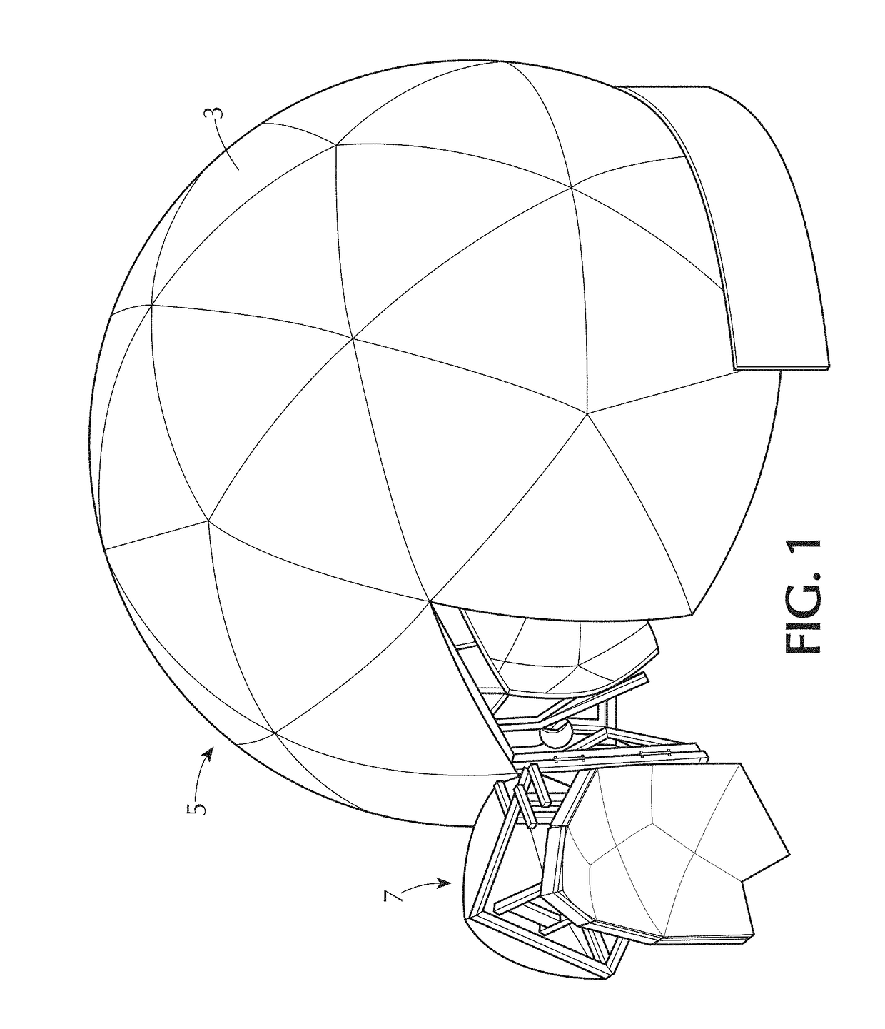
[0041]Referring to FIG. 1, a simulator system 3 according to the invention is shown. The system includes an external enclosure or spherical housing that surrounds the entire simulator and is shown indicated at 5. The external housing 5 includes a door area indicated at 7 that can be rotated away to allow access to the interior of the simulator 3.

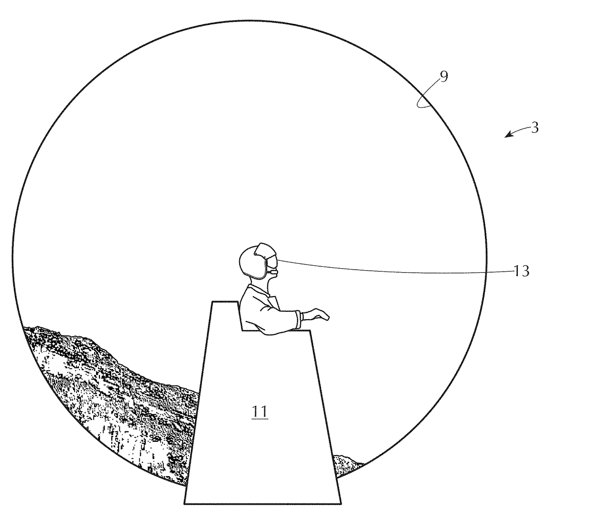
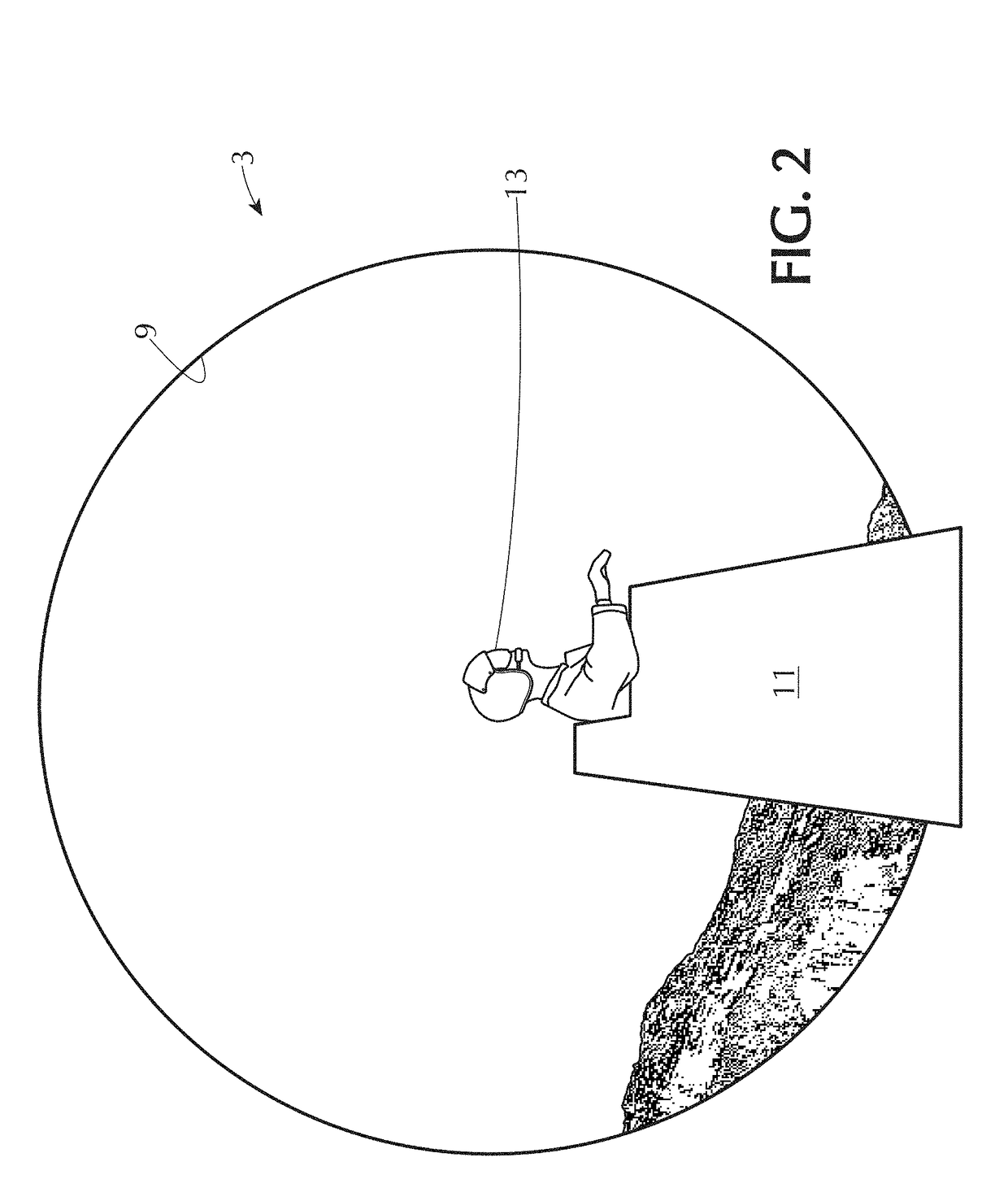
[0042]Referring to FIG. 2, inside the simulator 3, a spherical screen surface 9 is provided that extends around a user station 11. The user position is normally a simulated cockpit or a simulated vehicle control area on which the trainee sits or stands. The user station 11 is configured such that the eye of the trainee is preferably close to the geometrical center 13 of the sphere in which the surface of screen 9 lies. The geometrical centerpoint of this sphere is referred to as the design eyepoint.

[0043]In the preferred embodiment, the distance from the central design eyepoint indicated at 13 to the surface 9 is approximately six feet. Depe...


PUM


Abstract

A display system comprises a screen having a concave spherical surface positioned so as to be visible to a user of the system. The screen comprises a plurality of kite-shaped screen elements supported adjacent one another so as to form that spherical surface. Each of the screen elements comprises a respective faceplate comprising optical fibers extending adjacent each other so as to transmit light therethrough between two opposing face surfaces. One of the face surfaces is a concave spherical display image output surface, and the other of the face surfaces is a substantially planar image input surface. The screen elements also each comprise a respective image panel having a field of pixels each transmitting light corresponding to serial images of said panel. The fibers of the faceplate receive the light of the pixels of the image panel and together transmit the light from the image panel coherently to its image output surface so that the images of the panel are displayed on the image output surface.

Description

FIELD OF THE INVENTION[0001]The present invention relates to display systems, and especially to display systems with backlit display surfaces, and most particularly to spherical backlit systems for displaying out-the-window imagery to a user in a simulator.BACKGROUND OF THE INVENTION[0002]Simulators are used for training users in a variety of applications, as is well known in the art. Frequently, training in a simulator employs a simulator with a projection screen or dome screen onto which imagery is displayed for simulating the out-the-window (OTW) view in a simulated vehicle controlled by the trainee and moving in a virtual environment.[0003]One of the most common methods of creating this surrounding OTW imagery may be seen in U.S. Pat. No. 9,188,850 B2 or U.S. Pat. No. 6,552,699 B2, in which a number of rear-projection or backlit panels are organized and supported in a dome or sphere structure, i.e., a generally spherical screen arrangement that surrounds a training station at wh...

Claims


Application Information

Patent Timeline
IPC IPC(8): G03B21/60G02B6/06G02B6/26G03B37/04G03B37/06G09B9/30
CPCG03B21/60G02B6/06G02B6/262H04N9/315G03B37/06G09B9/302G03B37/04G02B6/08G03B21/62H04N9/3147G09F9/302G09F9/3026G09F9/305
Inventor CIPPANT, KEVIN P.GABEL, JONATHANTURNER, JAMES A.
Owner L 3 COMM CORP
Why Eureka
Try Eureka