
Testing device and method for testing a vibration motor arranged in a device

Active Publication Date: 2018-04-05
DRAGER SAFETY
View PDF8 Cites 1 Cited by
  • Summary
  • Abstract
  • Description
  • Claims
  • Application Information

AI Technical Summary

Benefits of technology

The technical effects of this patent text are to provide a simple testing device and method for testing vibration motors that are reliable and accurate, while minimizing false positive or false negative results. This solution can be easily integrated into existing testing devices without significant changes in configuration.

Problems solved by technology

Based on the imbalance, a mechanical vibration and shaking is induced during the rotation of the motor.

Method used


Image

  • Testing device and method for testing a vibration motor arranged in a device
  • Testing device and method for testing a vibration motor arranged in a device
  • Testing device and method for testing a vibration motor arranged in a device

Examples


Embodiment Construction

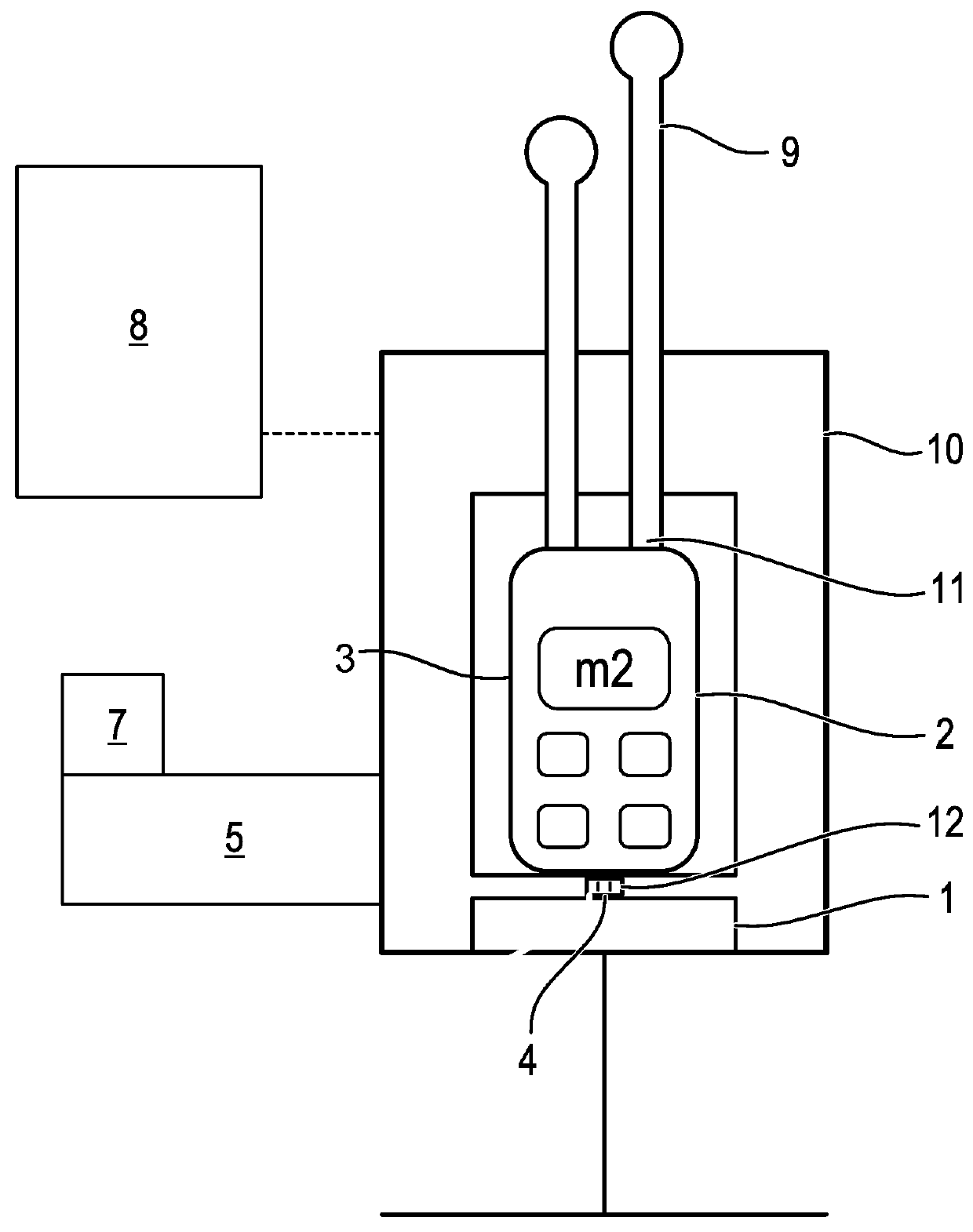
[0034]Referring to the drawings, FIG. 1 shows a schematic view of a testing device 1 configured according to the present invention for testing the ability of a vibration motor 2, which is arranged at a device 3, here a portable gas-measuring device, to function. The portable gas-measuring device 3 is located in a testing module 10 of the testing device 1 and is connected, on the one hand, to a test gas supply 9 of the testing device 1 via suitable gas ports 11. Further, contacts are provided as an electrical interface 12, via which the terminal voltage at the electrical terminal 6 of the vibration motor 2 can be detected. The testing device 1 has a sensor component 4 for this, which is configured according to this embodiment as a current- and / or voltage-measuring unit. The portable gas-measuring device 3 includes a tactile alarm means for generating a tactile alarm. The tactile alarm means comprises the vibration motor 2.

[0035]After the identification of the gas-measuring device 3 i...


PUM


Abstract

A method and a testing device (1) function test a vibration motor (2) arranged in a portable gas-measuring device (3). A sensor (4) detects a value for a motor property transmits the value to a control and analysis unit (5). The detected value is compared with a desired value, a test result is generated on the basis of the comparison, and a trigger signal is generated on the basis of the test result. A terminal voltage and / or current are determined during a switching-on and / or switching-off operation of the vibration motor (2) at an electrical terminal (6) of the vibration motor (2) on the basis of the motor property of the vibration motor (2). This terminal voltage and / or the terminal current present at least at times during the switching-on and / or switching-off operation are compared with at least one desired value in the control and analysis unit (5).

Description

CROSS REFERENCE TO RELATED APPLICATIONS[0001]This application claims the benefit of priority under 35 U.S.C. § 119 of German Application 10 2016 011 803.2, filed Oct. 4, 2016, the entire contents of which are incorporated herein by reference.FIELD OF THE INVENTION[0002]The present invention pertains to a testing device as well as to a method for testing a vibration motor arranged in a device. Such a testing device has at least one testing unit, with which at least one value for a property of the vibration motor is detected and transmitted to a control and analysis unit. The detected value is compared in this analysis unit with a desired value, a test result is generated on the basis of the comparison, and a signal, by which a subsequent action is triggered, is generated on the basis of the result.BACKGROUND OF THE INVENTION[0003]A plurality of testing devices, with which measuring devices are tested automatically for their ability to function properly, are known from the state of th...

Claims


Application Information

Patent Timeline
IPC IPC(8): G01R31/34H02K33/00G01N33/00
CPCG01R31/34H02K33/00G01N33/0009
Inventor SURIG, ANDREAS
Owner DRAGER SAFETY
Features
  • Generate Ideas
  • Intellectual Property
  • Life Sciences
  • Materials
  • Tech Scout
  • Unparalleled Data Quality
  • Higher Quality Content
  • 60% Fewer Hallucinations
Learn More