Internal combustion engine igniter

Active Publication Date: 2018-04-05
FUJI ELECTRIC CO LTD
View PDF0 Cites 7 Cited by
  • Summary
  • Abstract
  • Description
  • Claims
  • Application Information

AI Technical Summary

Benefits of technology

[0021]The igniter according to the present invention includes the heat-generation suppressing circuit that suppresses IGBT heat generation by increasing the current flowing to the IGBT in accordance with the intermediate voltage obtained by resistively dividing the auxiliary voltage. Then, when the IGBT operates abnormally for a prolonged period of time, the current flowing to the IGBT is increased by the heat-generation suppressing circuit even during current limiting by the current limiting circuit. As a result of this, it is possible to suppress the heat generation of the IGBT during current limiting, and to prevent the deterioration of ignition coil performance associated with the heat generation of the IGBT.
[0022]In particular, the heat-generation suppressing circuit only increases the current flowing to the IGBT by either increasing the voltage threshold of the current limiting circuit in accordance with the intermediate voltage, or increasing the gate voltage of the IGBT. Therefore, it is possible to use a simple configuration

Problems solved by technology

However, an IGBT 4 that satisfies all of these requirements would need to have a large device area and would be expensive.
However, when the above-mentioned current limiting controls are implemented during the occurrence of a prolonged abnormality lasting for 10 milliseconds or longer, for example, the collector voltage Vce of the IGBT 4 increases as a result o

Method used


Image

  • Internal combustion engine igniter
  • Internal combustion engine igniter
  • Internal combustion engine igniter

Examples


Embodiment Construction

[0029]The igniter according to the embodiments of the present invention will be explained below with reference to figures.

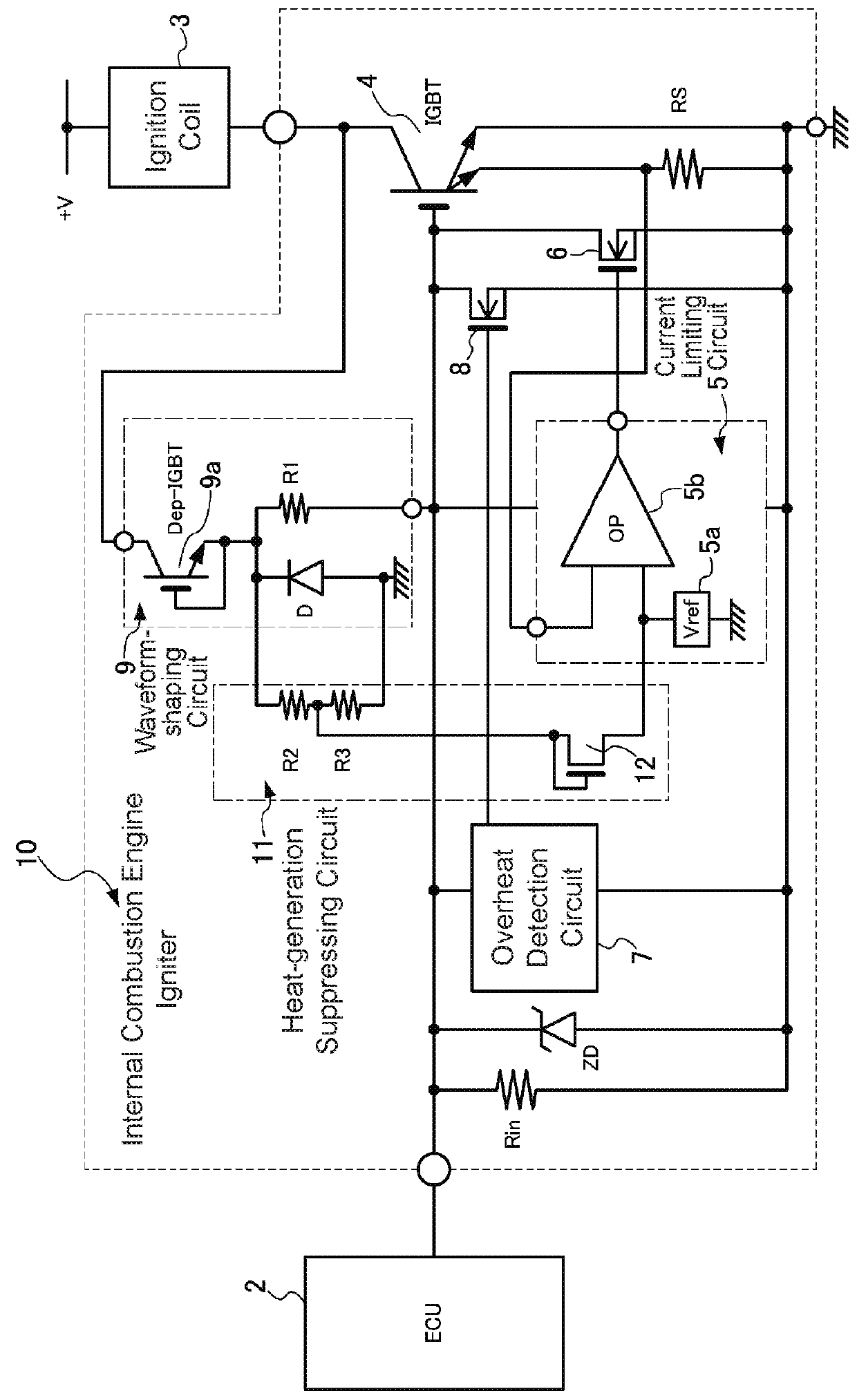
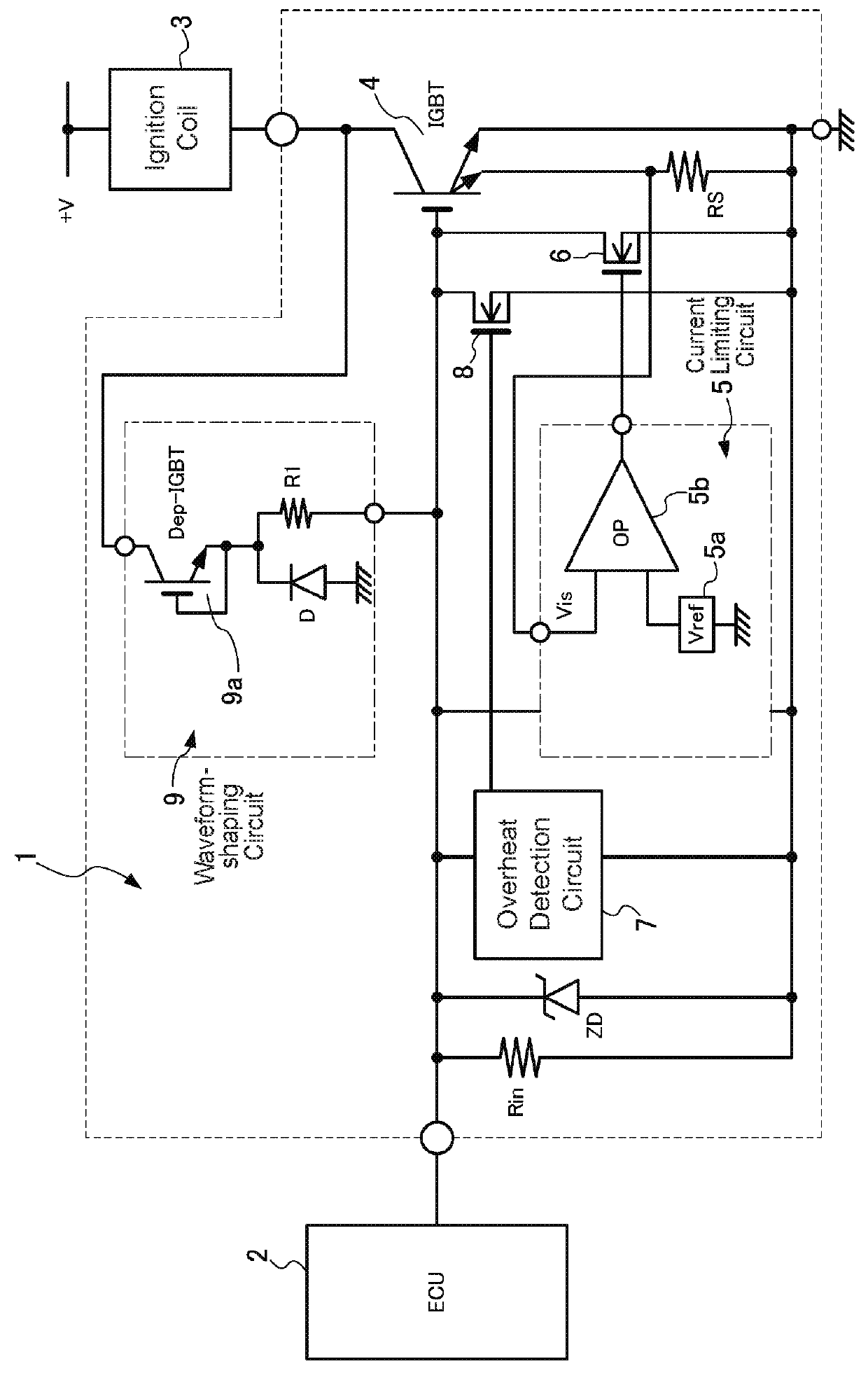
[0030]FIG. 1 is a diagram showing the overall configuration of an igniter 10 according to an embodiment of the present invention, and the same reference characters are given to the same portions as those in the conventional igniter 1 shown in FIG. 3. Furthermore, detailed explanations of the same portions as those in the conventional igniter 1 will be omitted.

[0031]In addition to the configuration of the conventional igniter 1, the igniter 10 according to this embodiment includes a heat-generation suppressing circuit 11 for coping with the occurrence of abnormalities that last for a relatively long time, such as 10 milliseconds or longer, for example. This heat-generation suppressing circuit 11 plays the role of suppressing IGBT heat generation by increasing the current flowing to an IGBT 4 in a state (during a current limiting operation) in which the current flo...


PUM


Abstract

An internal combustion engine igniter of the present invention includes a current limiting circuit that limits current flowing to the IGBT by controlling a gate voltage of the IGBT in accordance with the current flowing to the IGBT, a waveform-shaping circuit that suppresses an oscillation of the current flowing to the IGBT by applying to the gate voltage of the IGBT an auxiliary voltage generated from a collector voltage of the IGBT when current is being limited by the current limiting circuit, and, in addition, a heat-generation suppressing circuit that obtains an intermediate voltage by resistively dividing the auxiliary voltage generated by the waveform-shaping circuit when current is being limited by the current limiting circuit, and that suppresses IGBT heat generation by increasing the current flowing to the IGBT in accordance with the intermediate voltage.

Description

BACKGROUND OF THE INVENTIONTechnical Field[0001]The present invention relates to an internal combustion engine igniter of a simple configuration that is capable of preventing performance deterioration of an ignition coil resulting from prolonged abnormal operation of a power semiconductor device, e.g., an insulated-gate bipolar transistor (IGBT), that controls current flowing to the ignition coil.Background Art[0002]As shown in FIG. 3, for example, an internal combustion engine igniter 1 for controlling the ignition of the internal combustion engine includes a power semiconductor device 4 that controls current flowing to an ignition coil 3 in accordance with a control signal provided from an engine control unit (ECU) 2. An insulated-gate bipolar transistor (IGBT) is primarily used as this power semiconductor device 4. The IGBT 4 is disposed by being connected in series to a primary coil of the ignition coil 3, and plays the role of inducing a high voltage in a secondary coil of the ...

Claims


Application Information

Patent Timeline
IPC IPC(8): H03K17/082H01F38/12F02P11/00H02H7/20
CPCH03K17/0828H01F38/12F02P11/00H02H7/20F02P3/051F02P3/0552F02P3/053F02P3/055H03K2017/0806F02P3/0554F02P17/00
Inventor ISHII, KENICHI
Owner FUJI ELECTRIC CO LTD
Why Eureka
Try Eureka