Mobile wireless terminal
a mobile wireless terminal and wireless terminal technology, applied in the direction of resonant antennas, antenna earthings, electrostatic charges, etc., can solve the problems of significant deterioration of antenna characteristics, and achieve the effects of reducing the risk of electric shock, good antenna characteristics, and high impedan
- Summary
- Abstract
- Description
- Claims
- Application Information
AI Technical Summary
Benefits of technology
Problems solved by technology
Method used
Image

Examples
first preferred embodiment
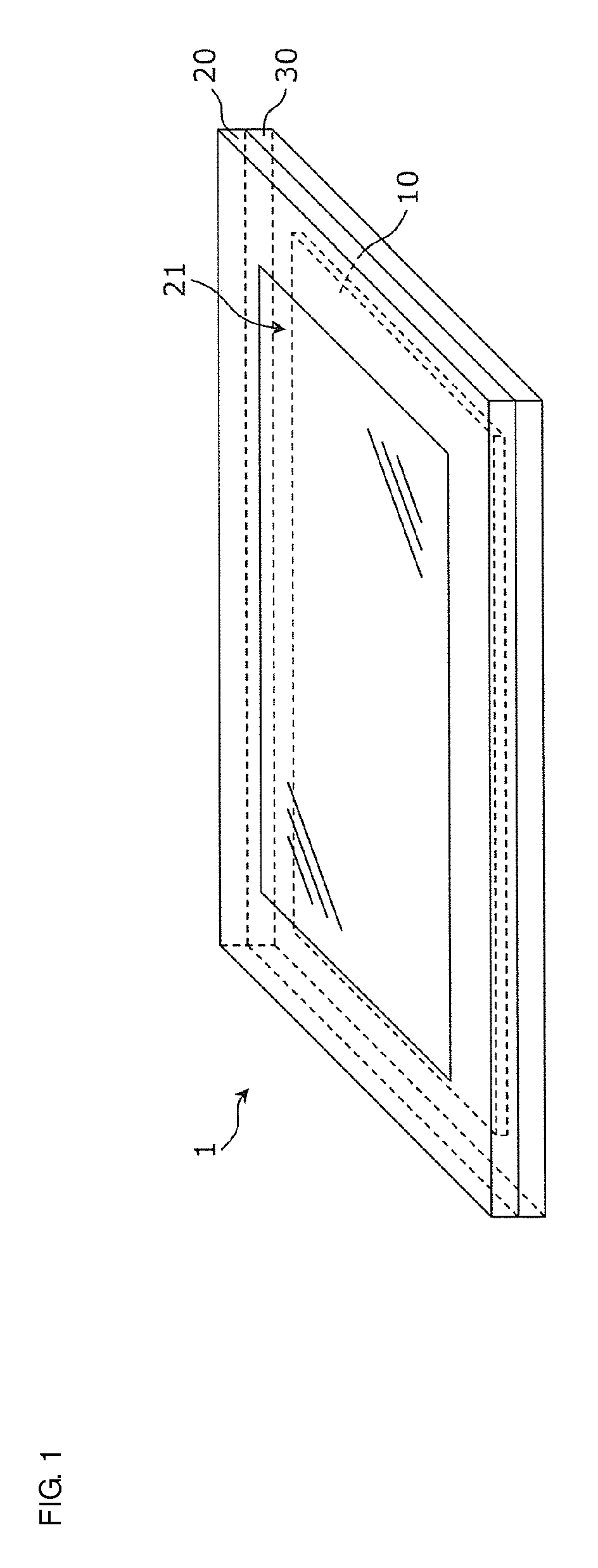
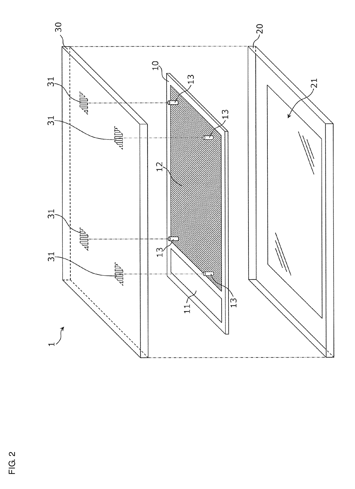
[0077]FIG. 7 is an exploded perspective view illustrating a structure of a mobile wireless terminal 1b according to a first preferred embodiment of the present invention. The mobile wireless terminal 1b differs from the mobile wireless terminal 1a of FIG. 4 in the structure and configuration of portion B. Specifically, an overcurrent protective element 16 that connects a ground conductor 12b and the land conductor 14 is included in portion B of a printed wiring board 10b. The overcurrent protective element 16 is thus connected to both of the ground conductor 12b and the metal casing 30 through the contact pin 13 and the land conductor 14, which are shared with the capacitor 15.
[0078]The overcurrent protective element 16 is an element having a nonlinear resistance value with respect to an applied voltage. Specifically, the overcurrent protective element 16 is a two-terminal element having a resistance value that drops abruptly in response to an applied voltage higher than or equal to...
second preferred embodiment
[0092]A second preferred embodiment of the present invention describes favorable conditions for the capacitance of the capacitors 15 and the capacitance of the overcurrent protective element 16.
[0093]To achieve good antenna characteristics, the capacitance of the overcurrent protective element 16 is preferably smaller than the capacitance of the capacitors 15. This is because of the following reasons.
[0094]FIG. 14 is a circuit diagram illustrating an equivalent connection circuit for antenna current, and corresponds to the connection circuit 19 of FIG. 9. As illustrated in FIG. 14, for antenna current, the capacitors 15 each equivalently include such components as an inductor L1, a capacitance C1, and a resistor R1, for example, and the overcurrent protective element 16 equivalently includes such components as an inductor L2, a capacitance C2, and a resistor R2, for example.
[0095]The overcurrent protective element 16 preferably includes a resistive component larger than that of the ...
third preferred embodiment
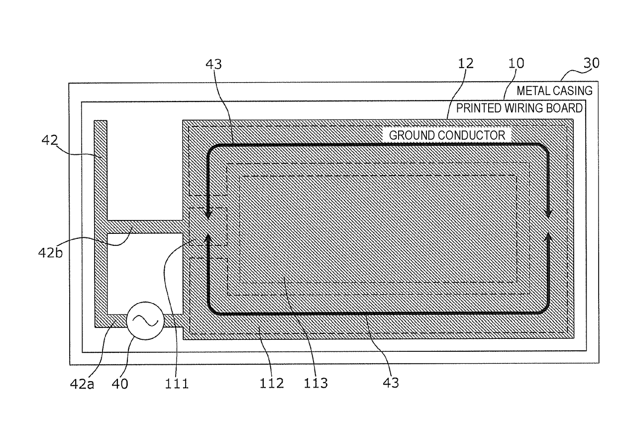
[0106]In a third preferred embodiment of the present invention, a preferable arrangement of the capacitors 15 and the overcurrent protective element 16 is described, which takes into account the distribution of antenna current in the ground conductor 12.
[0107]FIGS. 16 and 17 are top views each illustrating an example of antenna current flowing through the ground conductor 12. The metal casing 30 is disposed opposite the ground conductor 12. For simplicity and clarity, FIGS. 16 and 17 do not show the contact pins, the land conductors, the capacitors, and the overcurrent protective element.
[0108]In the examples of FIGS. 16 and 17, an inverted-L antenna conductor 41 or an inverted-F antenna conductor 42, for example, is preferably connected to one end of a feeder circuit 40, and the ground conductor 12 is connected to the other end of the feeder circuit 40. An antenna current is supplied to each of the antenna conductors 41 and 42 and the ground conductor 12 from the feeder circuit 40 ...
PUM
 Abstract
Description
Claims
Application Information
 - R&D
- Intellectual Property
- Life Sciences
- Materials
- Tech Scout
- Unparalleled Data Quality
- Higher Quality Content
- 60% Fewer Hallucinations
Browse by: Latest US Patents, China's latest patents, Technical Efficacy Thesaurus, Application Domain, Technology Topic, Popular Technical Reports.
© 2025 PatSnap. All rights reserved.Legal|Privacy policy|Modern Slavery Act Transparency Statement|Sitemap|About US| Contact US: help@patsnap.com