Motor vehicle lighting device with a ventilating device

a technology for motor vehicles and ventilating devices, which is applied in vehicle lighting systems, light and heating equipment, transportation and packaging, etc. it can solve the problems of unsatisfactory reliability of unattractive exterior, and inability to ensure the removal of condensed water droplets. , to achieve the effect of reducing the effectiveness of ventilation and defrosting, simplifying the desired replacement of air filters, and less complicated production of individual parts

Active Publication Date: 2018-04-19
AUTOMOTIVE LIGHTING REUTLINGEN GMBH
View PDF8 Cites 4 Cited by
  • Summary
  • Abstract
  • Description
  • Claims
  • Application Information

AI Technical Summary

Benefits of technology

[0020]This design has the advantage of a less complicated production of the individual parts. The individual parts can be produced, for example, in a production through injection molding of plastic, with less complex injection molds in comparison with the design in which the ventilating device is integrated in the housing.
[0021]In another embodiment, a fine mesh is provided at the air intake opening, so that insects or larger particles of dirt cannot enter the ventilating device. The releasable attachment also simplifies a desired replacement of an air filter. This is of particular advantage when the motor vehicle is operated over greater distances in dusty conditions. A gradually clogging filter could then reduce the effectiveness of the ventilation and defrosting. This undesired result can be avoided with little effort, by replacing the air filter.
[0022]The ventilating device may be disposed in a motor vehicle, in the intended use of the motor vehicle lighting device, such that it is spatially separated from the housing, and such that the motor vehicle lighting device has an air conducting connecting line, which connects the air outlet opening of the ventilating device to an interior space of the housing. This design has the advantage that the ventilating device can be installed, for example, at a location where a particularly high pressure buildup exists in front of the air intake opening when driving, which improves the effectiveness of the ventilation. Another advantage is that better use can be made of a tight installation space in the motor vehicle.
[0023]The housing may have a ventilation air outlet opening, and that an air filter is disposed in a flow path of the air exiting via the ventilation air outlet opening, directly in front of or behind the ventilation air outlet opening. It has proven to be the case that with some motor vehicles and some driving speeds, a pressure difference may exist at the ventilation air outlet opening, due to driving wind turbulences, which allows ambient air to enter the housing via the ventilation air outlet opening. The (second) air filter disposed there effectively prevents a contamination of the interior of the housing by dust in this case.

Problems solved by technology

In particular on the inner surface of the cover plate, condensed water drops can be seen from the exterior as an unattractive haze.
Some end customers assume wrongly that this is a defect and visit their dealers with complaints.
In extreme conditions, such as strong rain and spray from vehicles in front, a reliable removal of the condensed water droplets is not always ensured.

Method used


Image

  • Motor vehicle lighting device with a ventilating device
  • Motor vehicle lighting device with a ventilating device
  • Motor vehicle lighting device with a ventilating device

Examples


Embodiment Construction

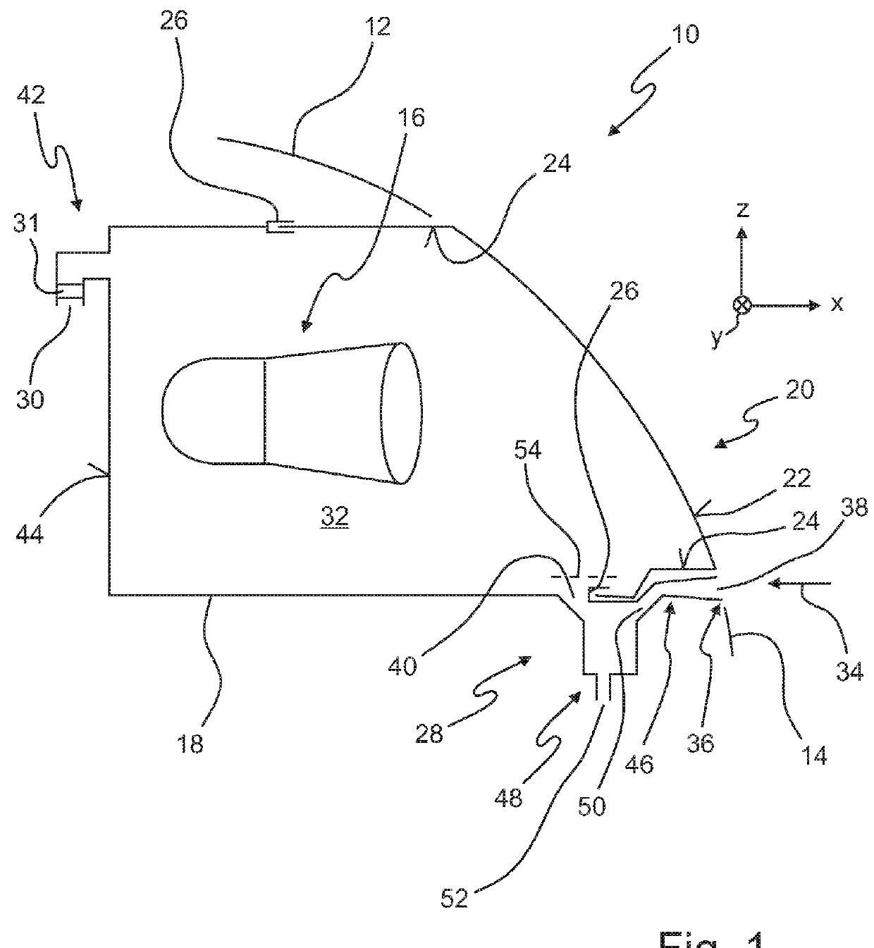
[0031]In detail, FIG. 1 shows an assembly composed of a motor vehicle lighting device 10 and at least one bordering part 12, 14, in a vertical cross section.

[0032]The bordering parts 12, 14 are parts of the vehicle body, for example, or parts of an adjacent motor vehicle lighting device, which has its own housing, or a cooler of the motor vehicle bordering on the motor vehicle lighting device 10. The configuration depicted therein is obtained with an intended use of the motor vehicle lighting device 10, in which the motor vehicle lighting device 10 is installed in a motor vehicle.

[0033]The cutting plane of the vertical cross section is the x-y plane of a right-handed and right-angled coordinate system, the x-axis of which corresponds to the longitudinal axis of the vehicle, the y-axis of which is at a right angle thereto, and parallel to the horizontal, and the z-axis of which is at a right angle to the x-axis and the y-axis, and extends vertically upward. This directional conventio...


PUM


Abstract

A motor vehicle lighting device has a housing and a ventilating device with an air supply line, which has an air intake opening, and which tapers away from the air intake opening in the form of a funnel, and which has an air outlet opening. The ventilating device includes a water collecting chamber, into which the air supply line opens with a transition cross section, and which has a water discharge opening and an air outlet opening, wherein the water discharge opening is disposed lower than the air outlet opening in an intended use of the ventilating device in a motor vehicle. A clearance of the water collecting chamber lying between the transition cross section and the air outlet opening is greater than the transition cross section.

Description

CROSS-REFERENCE TO RELATED APPLICATIONS[0001]The present application claims priority to and all the benefits of German Patent Application No. 10 2016 119 511.1, filed on Oct. 13, 2016, which is hereby expressly incorporated herein by reference in its entirety.BACKGROUND OF THE INVENTION1. Field of the Invention[0002]The present invention relates to a motor vehicle lighting device.2. Description of the Related Art[0003]Such a motor vehicle lighting device is known from DE 20 2014 008 530. The known motor vehicle lighting device has a housing and a ventilating device with air supply line, which has an air intake opening and tapers away from the air intake opening in the manner of a funnel. The ventilating device also has an air outlet opening. Ventilating air exiting the air outlet opening of the ventilating device enters the housing of the motor vehicle lighting device.[0004]Motor vehicle lighting devices are understood herein to be both headlamps as well as signal lights, in particu...

Claims


Application Information

Patent Timeline
Patent Type & Authority Applications(United States)
IPC IPC(8): F21S8/10
CPCF21S48/332F21S48/2212F21S43/26F21S45/30F21S41/28F21S48/1233
Inventor JAUERNIG, PETERSCHUBERT, UWEKINDLER, MARKUSMUEHLBAUER, BERNDBATHE, ACHIM
Owner AUTOMOTIVE LIGHTING REUTLINGEN GMBH
Why Eureka
Try Eureka