Escalator having common return rails

a technology of return rails and escalators, which is applied in the direction of escalators, transportation and packaging, etc., can solve the problems of long assembly time of escalators, high material costs for attaching materials, and the inability to create attachment locations on structural parts of escalators, etc., and achieve the effect of cost-effectiveness

Inactive Publication Date: 2018-05-03
INVENTIO AG
View PDF4 Cites 1 Cited by
  • Summary
  • Abstract
  • Description
  • Claims
  • Application Information

AI Technical Summary

Benefits of technology

[0007]The object of the present invention is to create an operationally reliable escalator comprising a cost-effectively configured return run.
[0008]This object is attained using an escalator comprising two deflection regions and a step belt arranged so as to circulate between the deflection regions, which step belt has pivotable steps. Their pivoting motions during the circulation are defined by step rollers or chain rollers and traction rollers as well as idling rollers that are arranged on both sides of the steps and roll on rails, wherein, because of the circulating arrangement, the step belt has a forward run used to convey persons and goods and a return run used to return the steps. To minimize material and assembly time, and therefore to minimize costs, a common return rail for the idling rollers and the step rollers is provided on each of the two sides of the step belt in the return run.
[0010]The bringing together or separation of step rollers and idling rollers in the transition region has the advantage, in particular, that the deflection regions have an installation height that at least does not exceed the installation heights of existing escalators.
[0017]In a third embodiment, the rotating conveyor device may have at least one conveying wheel that engages the step in the transition region. The conveying wheel essentially acts on the step in the same manner as the conveyor belt described in the foregoing. As soon as a step rear edge that is to be moved towards the conveying wheel touches the conveying wheel, the step body of the step is pivoted so that the idling roller is directed along the guide surface into the second guide rail. The shape or curves of the guide surface is / are preferably matched to the position and diameter of the conveying wheel so that the steps, when traveling through the transition region, are subjected to the least possible mechanical loads caused by the rotating conveyor device.
[0019]To further reduce mechanical loads caused by the rotating conveyor device, the rotating conveyor device or its conveyor rotors, conveyor belts, or conveying wheel may also be actively driven. For instance, the rotating conveyor device may be driven directly by the step belt. In this case, for instance, the movement of its traction means may be picked up mechanically and transmitted to the movable parts of the rotating conveyor device. A mechanical pick-up may be effected, for instance, by a chain wheel if the traction means is a link chain.

Problems solved by technology

This leads, first of all, to longer assembly times for the escalator, and, secondly, to higher material costs for attaching material and creating the attachment locations on structural parts of the escalator, such as, for example, frames, mounting plates, and the supporting structure.
The switch has the drawback that its switch tongue can get stuck due to soiling and wear.
This could endanger users and destroy parts of the escalator if the step rollers and idling rollers are no longer separated properly.
The rotating conveyor device can also cause noises that could unsettle the users of the escalator.
Since many escalators are used in department stores, the escalator should have as wide a step belt as possible and as narrow an installation width as possible so that the least possible amount of sales area is lost.

Method used


Image

  • Escalator having common return rails
  • Escalator having common return rails
  • Escalator having common return rails

Examples


Embodiment Construction

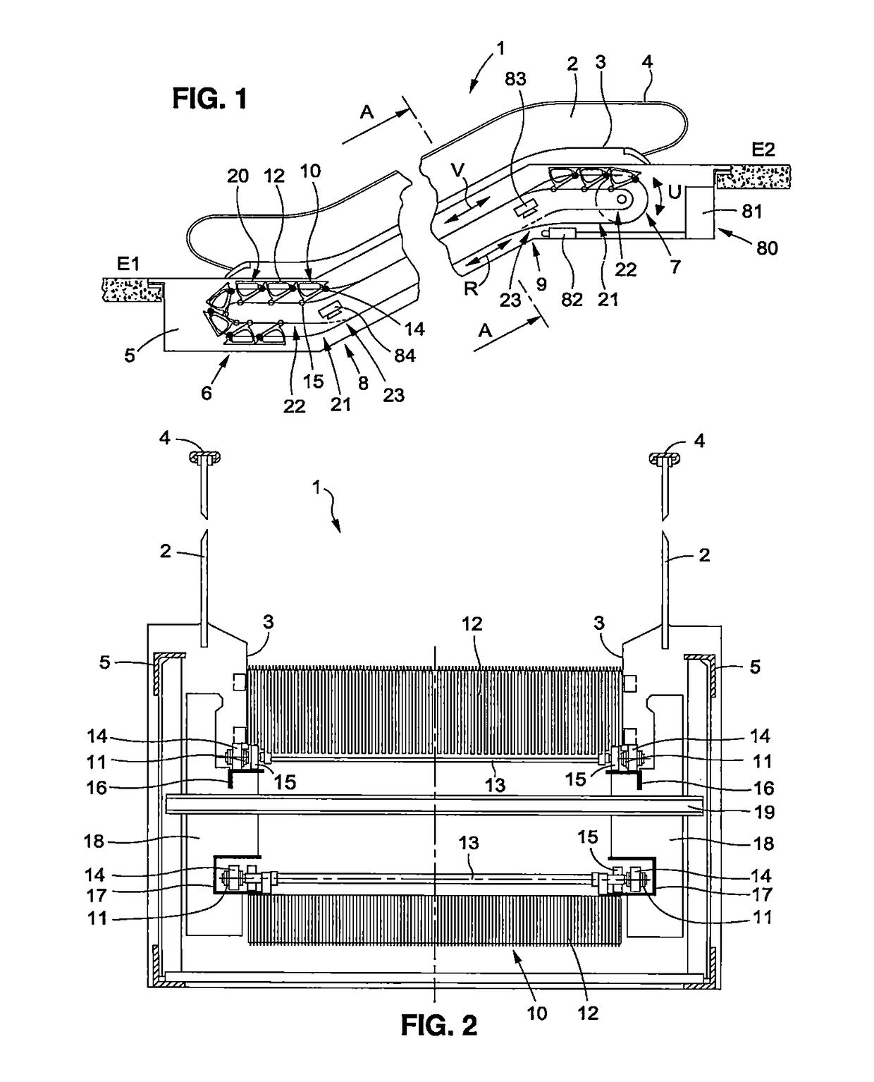
[0032]FIGS. 1 and 2 provide a schematic representation of an elevator 1 comprising a support structure 5 or truss 5 and two deflection regions 6, 7. The escalator 1 connects a first level E1 with a second level E2. A circulating step belt 10 is arranged in the support structure 5. The step belt 10 is bordered on the side by two balustrade bases 3 that extend in the longitudinal direction of the escalator 1 between the first level E1 and the second level E2. In addition, one circulating handrail 4 for each balustrade 2 is arranged on the balustrade base 3. The step belt 10 has at least one traction means 11 and a plurality of steps 12. Because of the circulating arrangement of the step belt 10, there is a forward run V used to convey persons and goods and a return run R used to return the steps 12.

[0033]The step belt 10 depicted in greater detail in FIG. 2 has one traction means 11, embodied as a link chain, on each side. Naturally, other traction means 11 such as, for example, belts...


PUM


Abstract

An escalator comprises two deflection regions and a step belt arranged so as to circulate between the deflection regions. The step belt has pivotable steps, the pivoting motions of the which are defined during the circulation by the step rollers and idling rollers arranged on both sides of the steps and rolling on rails. Because of the circulating arrangement of the step belt, there is a forward run used to convey persons and goods and a return run used to return the steps. Instead of two separate return rails per step belt side, a common return rail is used for the idling rollers and the step rollers on each of the two sides of the step belt in the return run.

Description

TECHNICAL FIELD[0001]The invention relates to an escalator comprising two deflection regions and a step belt arranged to circulate between the deflection regions. The step belt has pivotable steps, the pivoting motions of which during the circulation are defined by step rollers or chain rollers and idling rollers that are arranged on both sides of the steps and roll on rails. Because of the circulating arrangement, the step belt has a forward run used to convey persons and goods and a return run used to return the steps.DESCRIPTION OF RELATED ART[0002]Escalators of the type cited are described in WO 2013 / 010838 A1, for example. In the forward run of the step belt the deflection regions are also access regions for the step belt. To make it as easy and safe as possible to enter and leave the step belt, in these access regions, the tread surfaces of at least three successive steps are held on the same horizontal plane before the tread surfaces of the individual steps are displaced vert...

Claims


Application Information

Patent Timeline
Patent Type & Authority Applications(United States)
IPC IPC(8): B66B23/14
CPCB66B23/14B66B21/04
Inventor MATHEISL, MICHAELNOVACEK, THOMASWAGENLEITNER, GEORG
Owner INVENTIO AG
Why Eureka
Try Eureka