Gas turbine exhaust cooling system

a technology of exhaust cooling system and gas turbine engine, which is applied in the direction of machines/engines, mechanical equipment, light and heating apparatus, etc., can solve the problems of reducing the cooling effectiveness, high pressure loss in view, and high manufacturing cost of cooling holes, so as to reduce the interaction between the flows, reduce the effect of cooling efficiency, and prevent mixing

Active Publication Date: 2018-05-03
ROLLS ROYCE PLC
View PDF2 Cites 2 Cited by
  • Summary
  • Abstract
  • Description
  • Claims
  • Application Information

AI Technical Summary

Benefits of technology

[0008]Advantageously, by spacing the first outlet from the main fluid flow path by a second outlet, and by accelerating the second outlet exhaust cooling flow to a higher velocity than the first outlet cooling flow, shear interaction between the flows is minimised, t

Problems solved by technology

However, turbulence induced by shear from the relatively slow moving cooling air and the relatively fast (generally supersonic) core exhaust flow causes mixing between the flows, thereby reducing the effectiveness of the cooling.
This slow moving boundary air again interacts wi

Method used


Image

  • Gas turbine exhaust cooling system
  • Gas turbine exhaust cooling system

Examples


Embodiment Construction

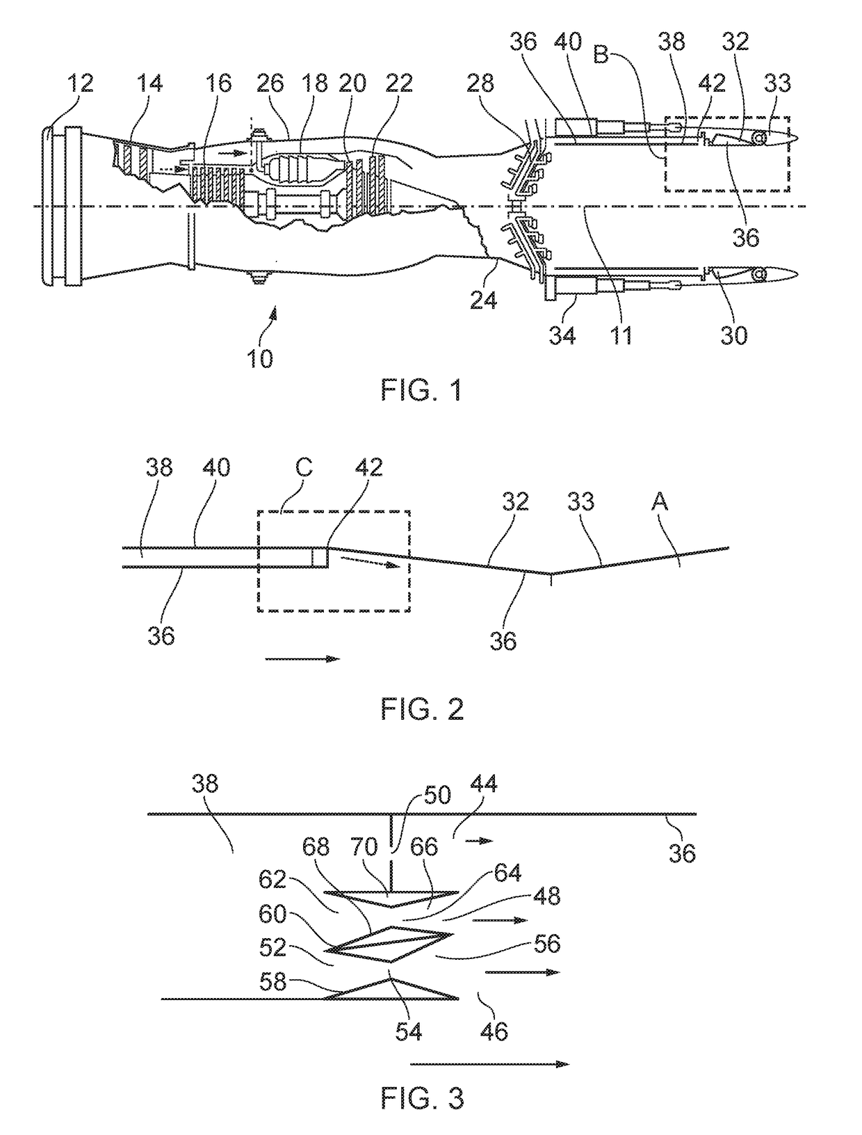
[0018]With reference to FIG. 1, a gas turbine engine is generally indicated at 10, having a principal and rotational axis 11. The engine 10 comprises, in axial flow series, an air intake 12, a propulsive fan 14, a compressor 16, combustion equipment 18, a high-pressure turbine 20, a low-pressure turbine 22 and an exhaust nozzle 20. A nacelle 21 generally surrounds the engine 10 and defines both the intake 12 and a mixing duct 24.

[0019]The gas turbine engine 10 works in the conventional manner so that air entering the intake 12 is accelerated by the fan 14 to produce two air flows: a first air flow (shown by a dotted arrow in FIG. 1) into the compressor 16 and a second air flow (shown by a solid arrow in FIG. 1) which passes through a bypass duct 26 to provide propulsive thrust. The compressor 16 compresses the air flow directed into it before delivering that air to the combustion equipment 18 where it is mixed with fuel and the mixture combusted. The resultant hot combustion product...


PUM


Abstract

A gas turbine engine (10) comprises a main fluid flow exhaust nozzle (30) bounding a main fluid flow path, and a cooling nozzle (38) provided upstream of the main fluid flow exhaust nozzle (30) in the main fluid flow path. The cooling nozzle (38) is arranged to provide cooling air to a surface (36) of the main fluid flow exhaust nozzle (30), the cooling nozzle (38) comprises first and second outlets (44, 46). The first outlet (44) is located adjacent the main fluid flow exhaust nozzle surface (36) and is spaced from the main fluid flow path by the second outlet (46). The second outlet (46) comprises a convergent divergent nozzle configured to accelerate cooling air exhausted from the second outlet (46) to a velocity greater than air exhausted from the first outlet (44).

Description

BACKGROUND OF THE INVENTION[0001]The present disclosure concerns a gas turbine engine comprising an exhaust cooling system.[0002]Components of aircraft gas turbines engines such as turbojets and turbofans typically reach high temperatures, and so may require cooling in order to prevent damage to components. In particular, gas turbine engines having afterburners (also known as “reheat”) may require cooling of the exhaust nozzle, to prevent damage to the nozzle itself.[0003]One prior gas turbine exhaust nozzle comprises a cooling channel which surrounds the gas turbine engine core in an annular arrangement (known as a “skirted ring”). Cooling air is provided from a compressor or bypass duct to the channel, which is then exhausted on to a downstream internal cooled surface of the core exhaust nozzle. The cooling air provides a cooling film, which shields the cooled surface from hot exhaust gasses. However, turbulence induced by shear from the relatively slow moving cooling air and the ...

Claims


Application Information

Patent Timeline
IPC IPC(8): F02K1/82F02K1/06F02C7/18
CPCF02K1/822F02K1/06F02C7/18F05D2220/32F05D2260/201Y02T50/60F02K3/10F23R3/18F02K3/08
Inventor STEELE, DAVID
Owner ROLLS ROYCE PLC
Why Eureka
Try Eureka