Method for detecting heart rate and heart rate monitoring device using the same

Inactive Publication Date: 2018-05-10
HTC CORP
View PDF2 Cites 0 Cited by
  • Summary
  • Abstract
  • Description
  • Claims
  • Application Information

AI Technical Summary

Benefits of technology

The present invention provides a method and device for detecting heart rate using emitted light. The device can adjust the light intensity faster to improve accuracy, overcoming a disadvantage of previous methods.

Problems solved by technology

However, it is time-consuming for the HRM device of the prior art to adjust the emitted light strength to a proper level.

Method used


Image

  • Method for detecting heart rate and heart rate monitoring device using the same
  • Method for detecting heart rate and heart rate monitoring device using the same
  • Method for detecting heart rate and heart rate monitoring device using the same

Examples


Embodiment Construction

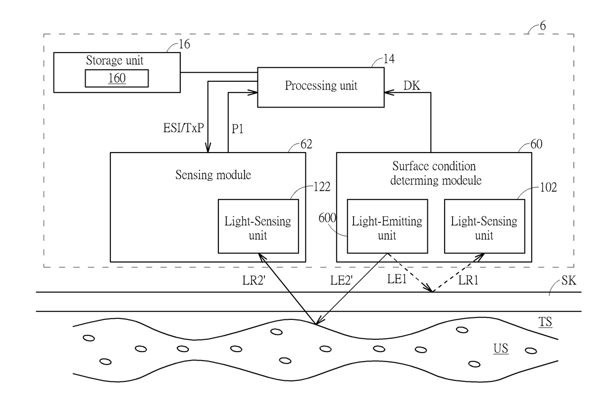
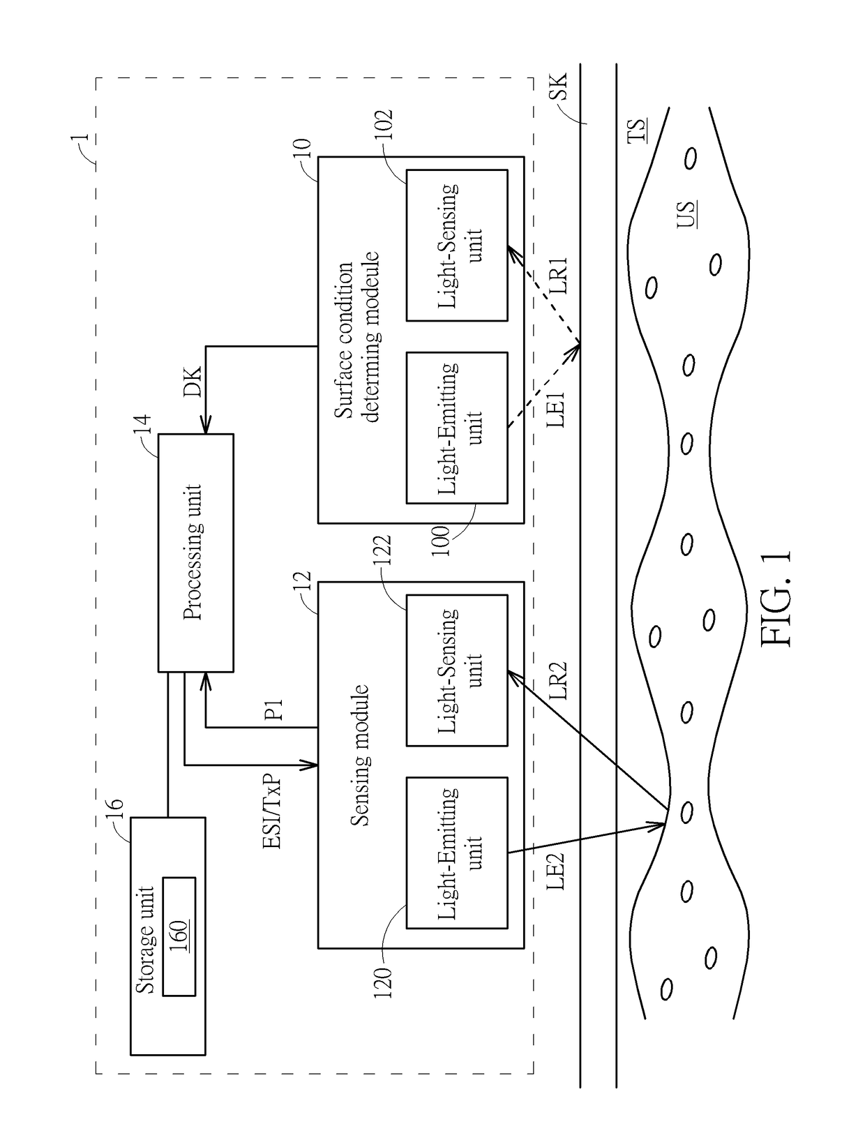
[0015]Please refer to FIG. 1, which is a schematic diagram of a heart rate monitoring (HRM) device 1 according to an embodiment of the present invention. The HRM device 1 may be a wearable electronic device such as a smart watch, a smart bracelet, a finger image sphygmomanometer, etc., configured to monitor a hear rate of a user / patient. The HRM device 1 comprises a surface condition determining module 10, a sensing module 12, a processing unit 14 and a storage unit 16. The sensing module 12 may be a photoplethysmogram (PPG) sensor, which is to generate a PPG signal P1. The processing unit 14 may determine the heart rate of the user / patient according to the PPG signal P1. The surface condition determining module 10 is configured to determine a darkness corresponding to a skin of a user, and accordingly generate a darkness result DK. A program code 160, stored in the storage unit 16, is configured to instruct the processing unit 14 to execute steps of a process. The processing unit 1...


PUM


Abstract

A method of controlling an emitted light strength for a heart rate monitoring (HRM) device is disclosed. The method includes steps of obtaining a surface condition of a skin of a user; determining an emitted strength of an emitted light according to the surface condition of the skin; and determining the heart rate of the user according to the emitted light with the emitted strength.

Description

BACKGROUND OF THE INVENTION1. Field of the Invention[0001]The present invention relates to a method for detecting a heart rate and a heart rate monitoring (HRM) device using the same, and more specifically, to a method for detecting a heart rate according to a surface condition of a skin, and an HRM device using the same.2. Description of the Prior Art[0002]Photoplethysmography (PPG) signal is developed to help people to monitor a peripheral hemal circulatory circumstance or a heart rate of a user / patient. PPG signal may be obtained by a noninvasive heart rate monitoring (HRM) device. As technology grows, the HRM device may be a wearable electronic device such as a smart watch or a smart bracelet.[0003]Specifically, the HRM device may comprise a PPG sensor. The PPG sensor emits an emitted light toward a skin of a user / patient, and a reflected light, reflected from the skin and received by the PPG sensor, is used to generate the PPG signal. In the prior art, the HRM device would grad...

Claims


Application Information

Patent Timeline
IPC IPC(8): A61B5/024G06T7/00G06T7/40
CPCA61B5/02427G06T7/0012G06T2207/30088A61B2560/0242G06T7/408A61B5/02438A61B5/681A61B5/6824A61B5/0077A61B5/02416A61B5/1032A61B5/441A61B5/7225A61B2560/0223G06T7/90
Inventor KAO, CHEN-HUA
Owner HTC CORP
Why Eureka
Try Eureka