
Concentrated indoor cold supply system for residential districts

A concentrated room and cooling system technology, applied in air conditioning systems, household heating, space heating and ventilation, etc., can solve the problems of exacerbating high temperature and heat, stuffy surrounding environment, and resource consumption, so as to alleviate the contradiction between supply and demand of energy and save energy. Power consumption, the effect of ensuring effective work

Inactive Publication Date: 2015-08-05
高忠义
View PDF5 Cites 0 Cited by
  • Summary
  • Abstract
  • Description
  • Claims
  • Application Information

AI Technical Summary

Problems solved by technology

Although the cooling effect of the air conditioner is good, there are still some problems. Firstly, it consumes a lot of energy when used alone; secondly, the air conditioner continuously discharges heat during the cooling process, making the surrounding environment more stuffy, which invisibly aggravates the high temperature and heat The third is that a large number of air conditioners will increase the cross-sectional area of ​​the power line of the indoor electrical box, and the capacity of the transformer in the substation and distribution room of the community will also increase, which will increase the construction cost and consume resources; The beautification of indoor and outdoor buildings is affected, and more or less affects the architectural pattern of buildings

Method used


Image

  • Concentrated indoor cold supply system for residential districts
  • Concentrated indoor cold supply system for residential districts
  • Concentrated indoor cold supply system for residential districts

Examples


Embodiment Construction

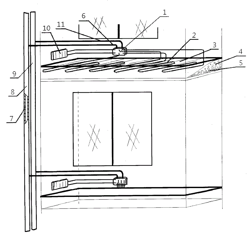
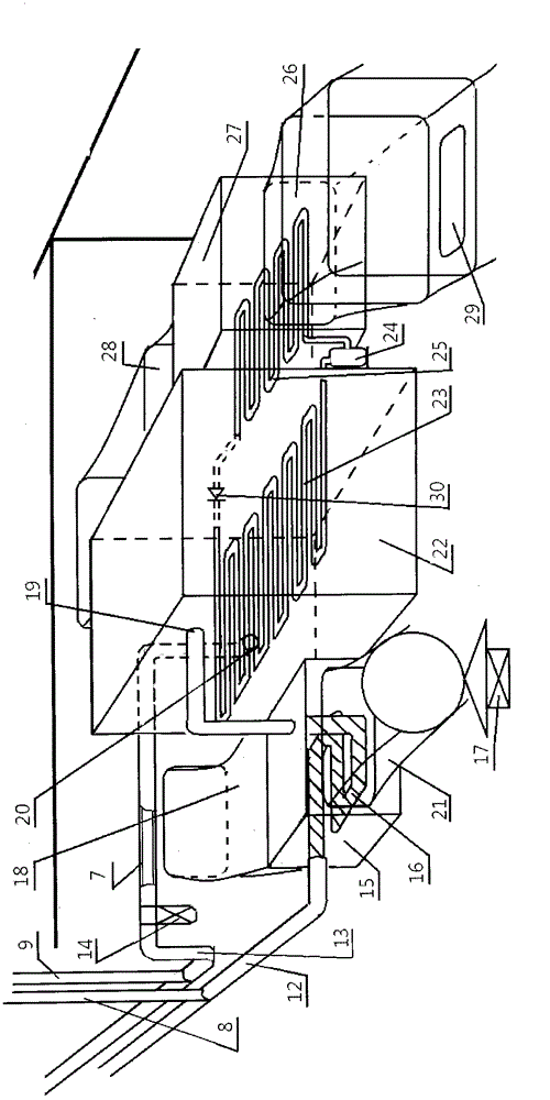
[0010] The invention is composed of a cold water circulation system, a chiller refrigeration circulation system, a seawater or river water cooling system and a large-scale chiller power supply system. The cold water circulation system is divided into two parts, one part is paved with gravel (5) on the cement floor indoors among the users in the residential area, and spread out, and several thermally conductive water pipes are placed according to the size of the indoor area. (2) spread evenly on the gravel (5) side by side, then fix the heat-conducting water pipe (5) with cement mortar (4) and smooth the surface, and lay a heat-conducting floor (3) on the surface to form ground cooling; One end of the thermally conductive water pipe (2) is respectively connected to the water supply port of the water separator (1), and the other end of the thermally conductive water pipe (2) is respectively connected to the water return port of the water separator (1). It can also be installed on...


PUM


Abstract

A concentrated indoor cold supply system for residential districts consists of a cold water circulation system, a cold water mechanism cold circulation system, a seawater or riverwater cooling system and a large-scale cold water unit power supply system. Pipelines for urban residential districts can be connected with one another to form a network, and users make ground-cooling floors by using heat conduction water pipes and floors and the like; a large-scale cold water unit is used for industrialized refrigeration, the large-scale cold water unit and other equipment are arranged in an underground workshop; a cooling tank and a pipeline are arranged below lowest water level of seawater or riverwater, and by using tide and naturally flowing water resource of riverwater on wet season, the cooling tank is cooled to effectively work; a wind power generation system issued for supplying power for the large-scale cold water unit, and the two establish a supply and distribution relation without changing the supply and distribution relation of power and load of an original power grid system. According to the concentrated indoor cold supply system for the residential districts, natural laws and clean energy are fully used, heat exchanged from indoor in a refrigeration process is fundamentally brought away, and the aim of low carbon and environment friendliness are achieved.

Description

technical field [0001] The invention belongs to the technical field of design and manufacture of room cooling Background technique [0002] In summer, most cities in southern my country are always plagued by high temperature and heat for quite a long period of time. The temperature can reach above 38°C at the hottest time, which brings a lot of inconvenience to people's life and work. Everyone is thinking To improve the living environment, most of the current market uses air conditioners to cool down the room. Due to the peak period of electricity consumption, the power consumption of air conditioners is very large, which puts a lot of pressure on the power supply of the grid system, and the contradiction between supply and demand of energy will be highlighted immediately. Although the cooling effect of the air conditioner is good, there are still some problems. Firstly, it consumes a lot of energy when used alone; secondly, the air conditioner continuously discharges heat d...

Claims


Application Information

Patent Timeline
Patent Type & Authority Applications(China)
IPC IPC(8): F24F5/00F24F13/02
CPCY02B10/40F24F5/0003F24F13/02
Inventor 高忠义
Owner 高忠义
Learn More