Element assembly and filter

a technology of elements and filters, applied in the direction of machines/engines, positive displacement liquid engines, separation processes, etc., can solve the problems of sharp increase in airflow and inability to improve achieve the effect of improving the efficiency of removing foreign matter, such as liquid, oil, dust and dus

Active Publication Date: 2018-05-10
KOGANEI
View PDF17 Cites 3 Cited by
  • Summary
  • Abstract
  • Description
  • Claims
  • Application Information

AI Technical Summary

Benefits of technology

[0008]An object of the present invention is to provide a filter that removes foreign matters with high efficiency.
[0011]The element assembly has the filter element and the air guide member provided inside the filter element. The compressed air filtered through the filter element flows through the slit and is jetted toward the inner surface of the air guide member. Liquid and oil contained in the air-to-be-treated collide and agglomerate as they are filtered through the filter element, and grow into droplets of certain sizes. The droplets grown into certain sizes flow downward along an inner wall of the filter element, and are accumulated in a storage chamber. Some of the droplets detach from the inner wall of the filter element along with the flow of the compressed air, collide against an outer wall of the air guide member, and adhere to this outer wall. The droplets adhered to the outer wall flow downward toward the storage chamber by their own weight. Additionally, the droplets flowed through the slit formed on the air guide member flow in a circumferential direction of the air guide member, collide against the inner surface of the air guide member, adhere to this inner surface, and flow downward toward the storage chamber by their own weight. No droplets, therefore, flow toward the outflow port. Thus, efficiency of removing foreign matters, such as liquid, oil, and dust, can be improved.

Problems solved by technology

However, a sudden change, or more specifically, a sudden increase in an amount of consumption of the compressed air on a secondary-side of the filter causes a flow rate of air to increase sharply.
If the droplets are mixed with the compressed air, efficiency of removing foreign matters cannot be improved.

Method used


Image

  • Element assembly and filter
  • Element assembly and filter
  • Element assembly and filter

Examples


Embodiment Construction

[0029]Hereinafter, embodiments of the present invention will be described in detail with reference to the drawings. In the drawings, components that are the same as each other are denoted by the same reference numerals.

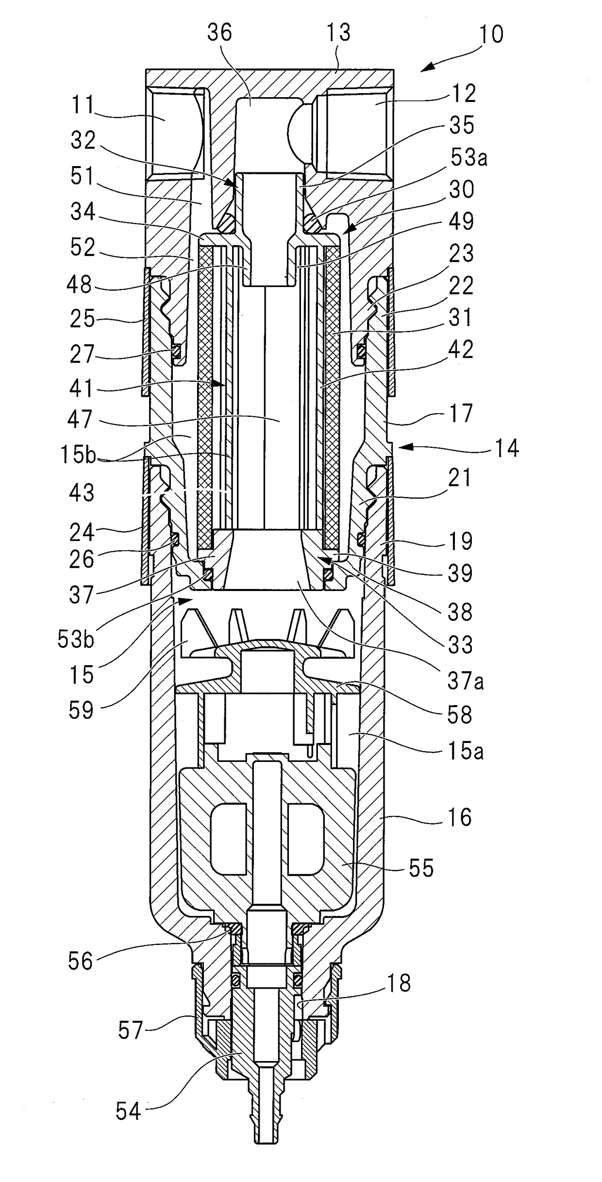
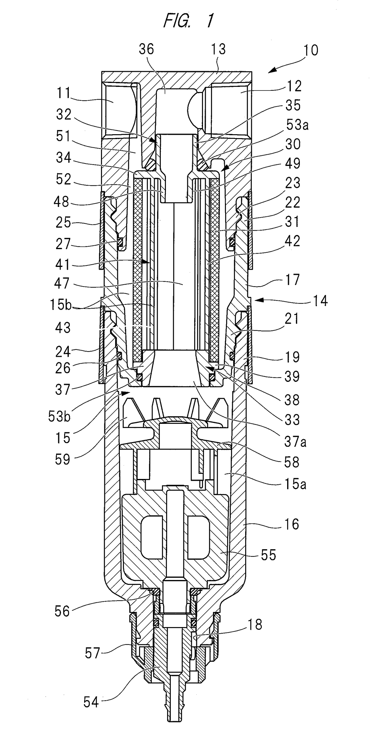
[0030]A filter 10 shown in FIG. 1 has a port block 13 provided with an inflow port 11 and an outflow port 12. The inflow port 11 is connected to an air guide member, such as piping or a hose, and air-to-be-treated is supplied to the filter 10 through the air guide member. The outflow port 12 is connected to an air guide member, such as piping or a hose, and purified compressed air flows out through the outflow port 12.

[0031]The filter 10 has a filter container 14 detachably attached to a lower end portion of the port block 13. The filter 10 is used with the port block 13 located on an upper side of the filter 10, and with the filter container 14 located on a lower side of the filter 10. The port block 13 of the filter 10 is mounted to a wall surface (not shown), or th...


PUM

PropertyMeasurementUnit
angleaaaaaaaaaa
diameteraaaaaaaaaa
Sizeaaaaaaaaaa

Abstract

A filter (10) has a port block (13) provided with: an inflow port (11) to which compressed air is supplied; and an outflow port (12) from which purified compressed air flows out. A filter container (14) is attached to the port block (13), and an element assembly (30) is disposed inside the filter element (31). The element assembly (30) has: a filter element (31); and an air guide member (41) provided inside the filter element (31). The compressed air filtered through the filter element (31) is guided to an inner surface of the air guide member (41) through a slit (46).

Description

CROSS-REFERENCE TO RELATED APPLICATIONS[0001]This application is a National Stage application of International Patent Application No. PCT / JP2015 / 074096, filed on Aug. 26, 2015, which claims priority to Japanese Patent Application No. 2015-063534, filed on Mar. 26, 2015, each of which is hereby incorporated by reference in its entirety.TECHNICAL FIELD[0002]The present invention relates to an element assembly and a filter utilized for removing foreign matters, such as liquid and dust, contained in compressed air to be supplied to a pneumatic device.BACKGROUND ART[0003]Compressed air is supplied from a pneumatic source to a pneumatic device, such as a pneumatic cylinder, through a pneumatic line, such as piping or a hose. The pneumatic source and the pneumatic device are connected to each other through the pneumatic line, thereby forming a pneumatic circuit. Compressed air to be supplied from the pneumatic source to the pneumatic device is regarded as “air-to-be-treated”, and the pneum...

Claims


Application Information

Patent Timeline
Patent Type & Authority Applications(United States)
IPC IPC(8): B01D45/12B01D46/00F04B39/16B01D46/42
CPCB01D45/12B01D46/0005F04B39/16B01D46/0031B01D46/4272B01D46/0039B01D46/2411B01D45/08B01D46/0049
Inventor YAMAUCHI, TAKESHI
Owner KOGANEI
Why Eureka
Try Eureka