Lane Departure Prevention System of Vehicle
a technology of lane departure prevention and vehicle, which is applied in the direction of vehicle components, control devices, driver input parameters, etc., can solve the problems of vehicle oversteering behavior, vehicle may enter a spinning state, and the lateral force of the turning inside wheel may be insufficient, so as to reduce the likelihood
- Summary
- Abstract
- Description
- Claims
- Application Information
AI Technical Summary
Benefits of technology
Problems solved by technology
Method used
Image
Examples
first embodiment
Operation in First Embodiment
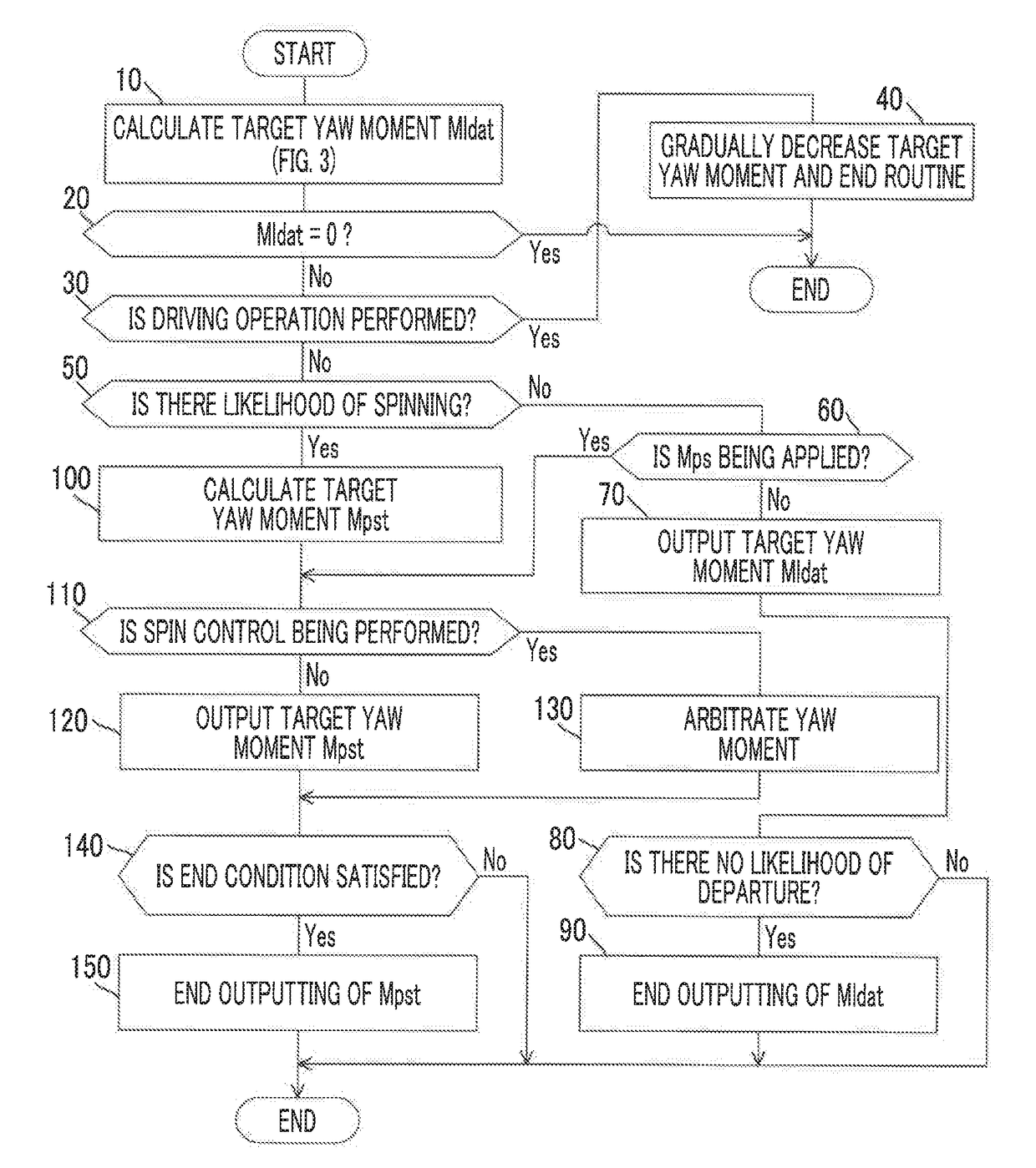
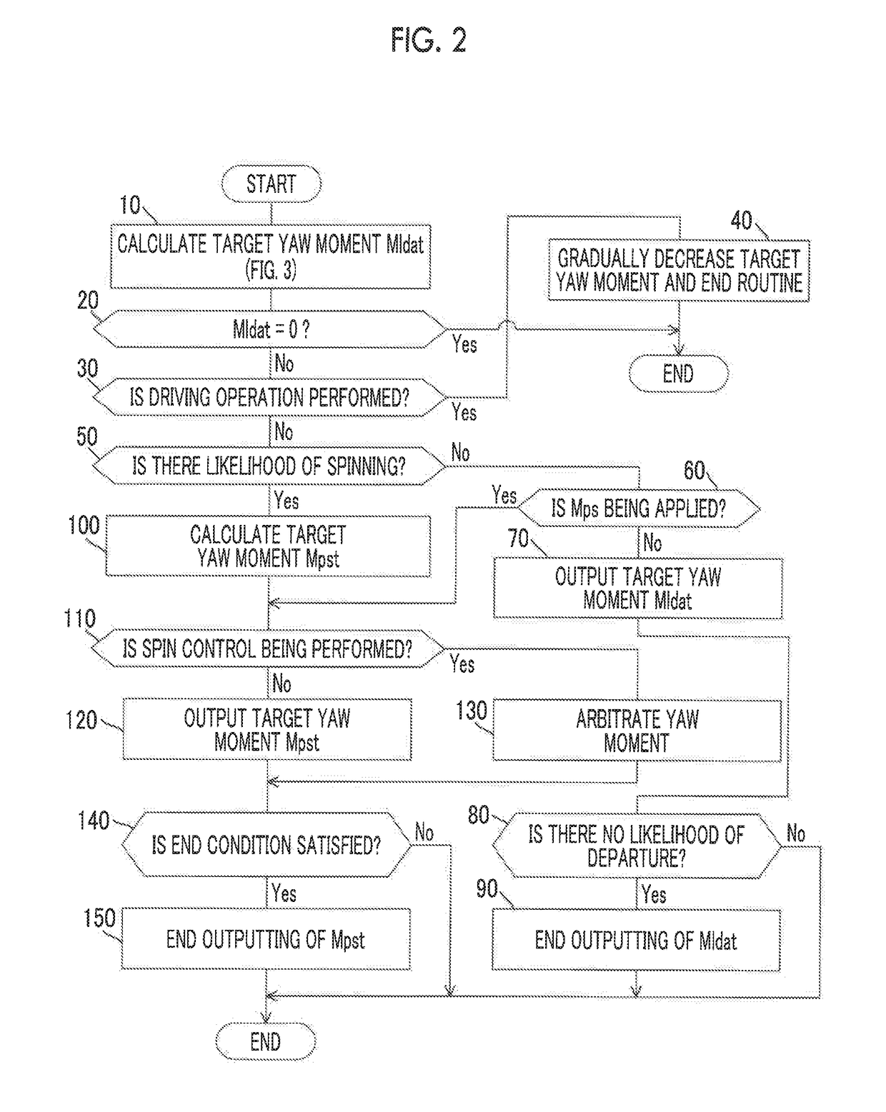
[0123]An operation in the first embodiment in a situation in which a driving operation is not performed by a driver will be described below. When a driving operation is performed by a driver, the determination result of Step 30 is positive, and the lane departure prevention yaw moment Mlda and the spin prevention yaw moment Mps decrease gradually to be zero or is kept at zero by performing Step 40. Operations in second and third embodiments which will be described later are the same as the operation in the first embodiment except points which will be particularly mentioned later.
[0124](X) Case in which There is No Likelihood of Departure from a Lane and There is No Likelihood of Spinning
[0125]When there is no likelihood that the vehicle 18 will depart from the lane to the turning outside and there is no likelihood that the vehicle 18 will enter a spinning state, the target lane departure prevention yaw moment Mldat is calculated to be zero in Step 10. Ac...
second embodiment
[0141]In a second embodiment, the lane departure prevention control is performed in the same way as in the first embodiment in accordance with the flowcharts illustrated in FIGS. 2 and 3 except for Steps 100 and 140.
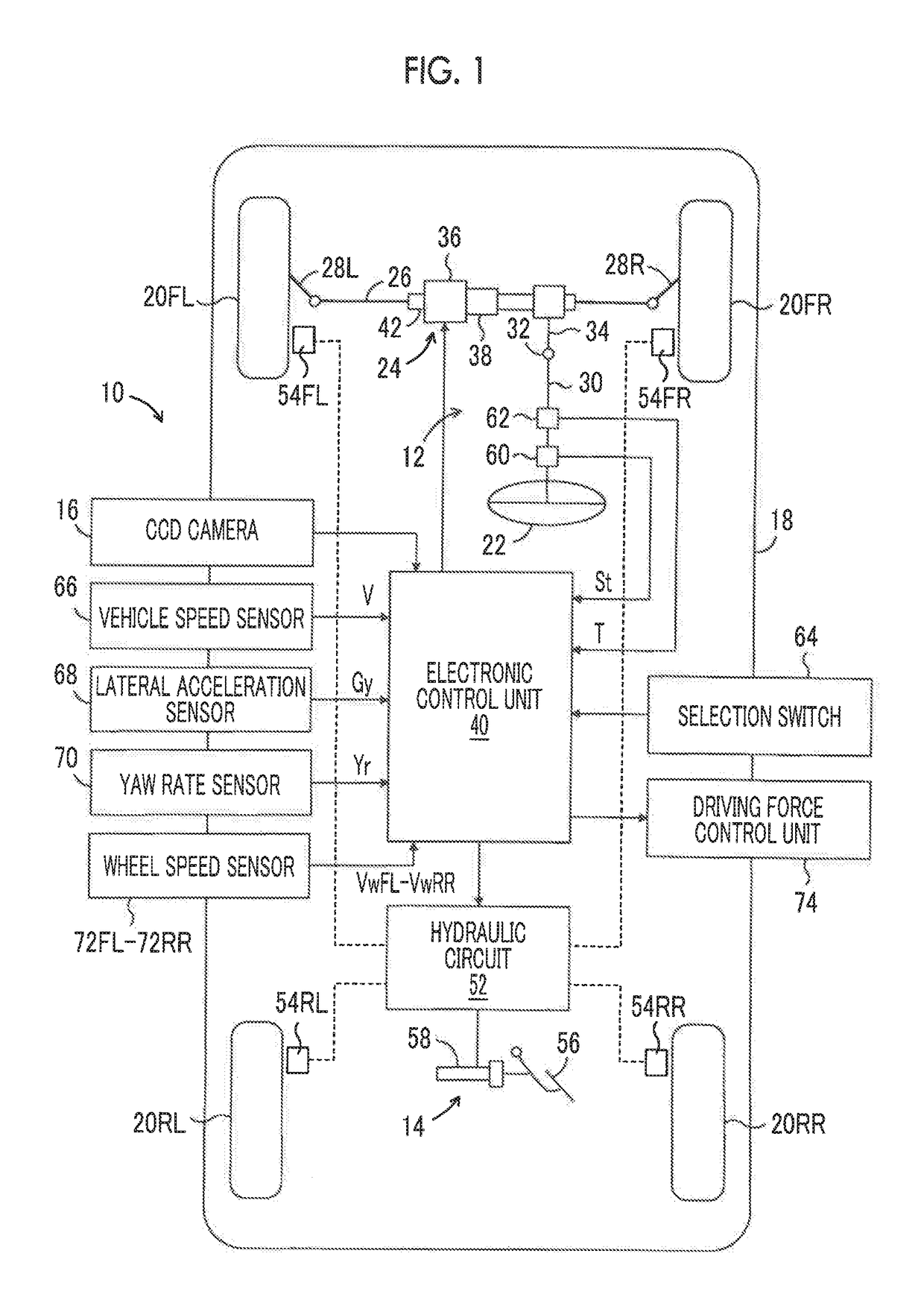
[0142]In Step 100 in the second embodiment, similarly to the first embodiment, the target yaw moment Mpst, the phase-compensated normative yaw rate Yrvcf of the vehicle, and the phase-compensated normative lateral acceleration Gyvcf of the vehicle are calculated. The yaw rate Yr and the lateral acceleration Gy of the vehicle detected by the yaw rate sensor 70 and the lateral acceleration sensor 68 are stored as a reference value Yrr of the yaw rate and a reference value Gyr of the lateral acceleration in the RAM.
[0143]In Step 140, an end reference value ΔYre of the yaw rate is calculated with reference to the map illustrated in FIG. 10 based on the reference value Yrr of the yaw rate. An end reference value ΔGye of the lateral acceleration is calculated with reference to...
third embodiment
[0145]In a third embodiment, the lane departure prevention control is performed in the same way as in the first embodiment in accordance with the flowcharts illustrated in FIGS, 2 and 3 except for Steps 100 and 140.
[0146]In Step 100 in the third embodiment, the target yaw rate Yrnf is calculated by Equation (2) or (4). The target spin prevention yaw moment Mpst is calculated with reference to the map illustrated in FIG. 12 based on the difference ΔYr (=Yrnf−Yr) between the target yaw rate Yrnf and the actual yaw rate Yr. Similar to the first and second embodiments, the phase-compensated normative yaw rate Yrvcf of the vehicle and the phase-compensated normative lateral acceleration Gyvcf of the vehicle are also calculated.
[0147]In Step 140, for example, when all the above-mentioned conditions (G) and (H) and the following condition (K) are satisfied, it may be determined that the end conditions are satisfied. Condition (G) may be omitted when Condition (A) is omitted, or Condition (...
PUM
 Abstract
Description
Claims
Application Information
 - R&D
- Intellectual Property
- Life Sciences
- Materials
- Tech Scout
- Unparalleled Data Quality
- Higher Quality Content
- 60% Fewer Hallucinations
Browse by: Latest US Patents, China's latest patents, Technical Efficacy Thesaurus, Application Domain, Technology Topic, Popular Technical Reports.
© 2025 PatSnap. All rights reserved.Legal|Privacy policy|Modern Slavery Act Transparency Statement|Sitemap|About US| Contact US: help@patsnap.com


