

Battery Leasing and Wireless Power Transfer for Passenger Rail
a passenger rail and wireless technology, applied in the direction of electric devices, machines/engines, rail devices, etc., can solve the problems of large capital expenditure, inability to fully realize the full cycle and the finite life of the battery cell much shorter, so as to increase the time of power transmission by 50% and double the amount of energy transferred to the train
- Summary
- Abstract
- Description
- Claims
- Application Information
AI Technical Summary
Benefits of technology
Problems solved by technology
Method used
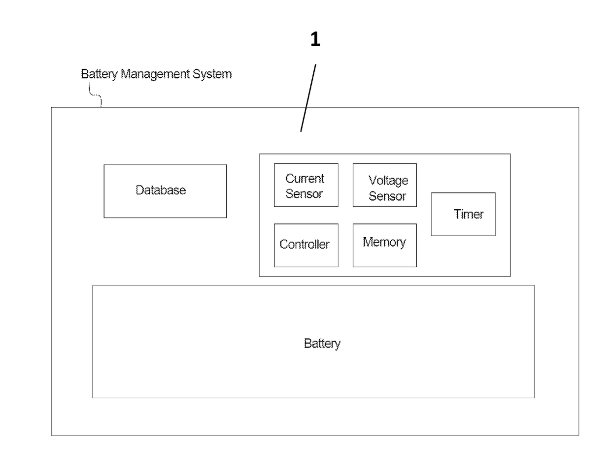
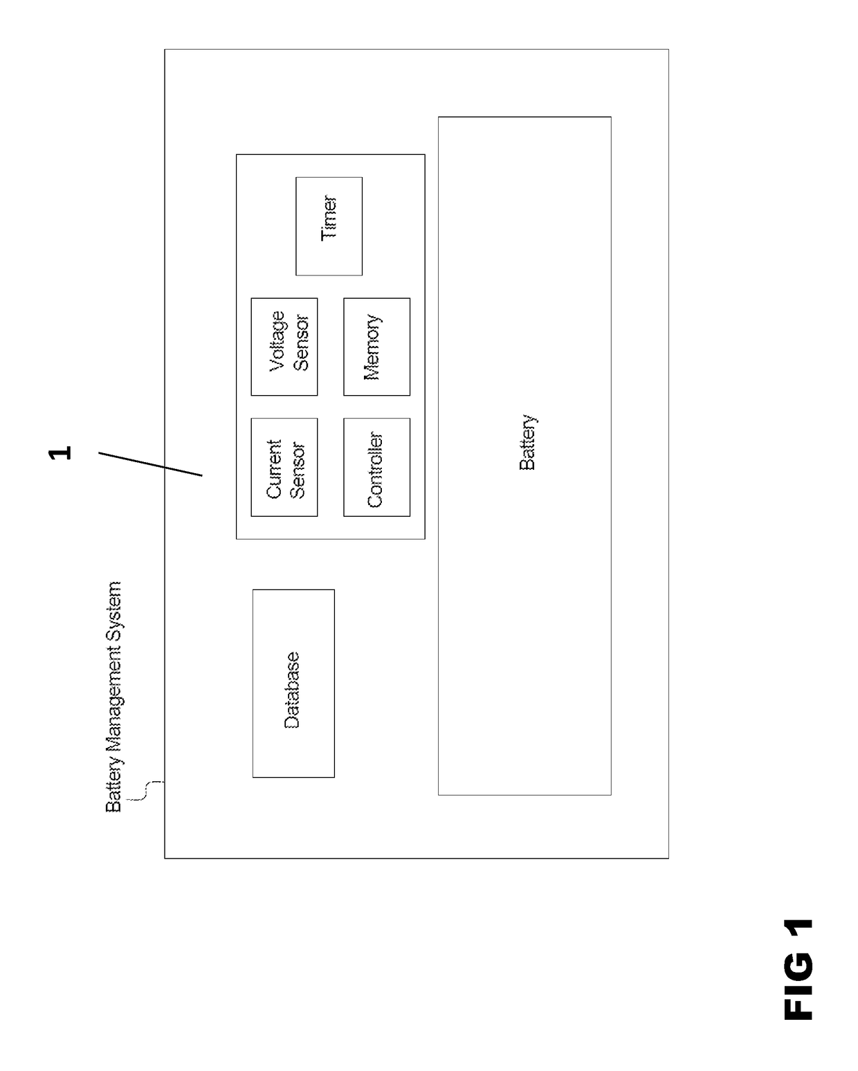
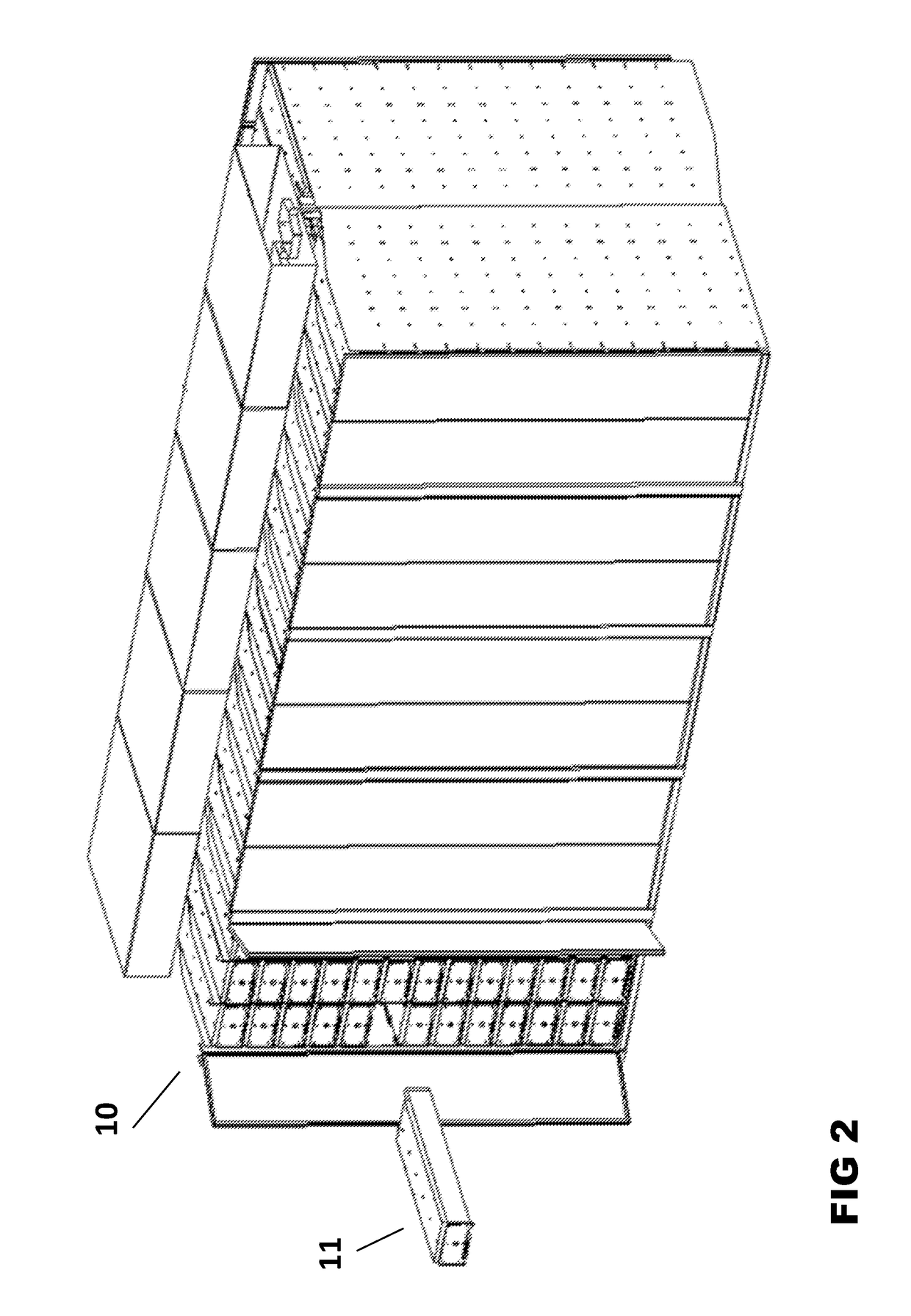
Image

Examples
Embodiment Construction
[0040]To facilitate an understanding of the present disclosure, a number of terms and phrases are defined below:
[0041]‘A-B’ Unit: During the transition from steam power to diesel power in the railroad industry, the early diesel locomotives were less powerful than steam locomotives, and the diesel engines were less efficient and less reliable than current medium speed diesel engines. Because of this, it was rare to have a single diesel powered locomotive in a consist. It was so common to have additional locomotives in train consists that many locomotives were produced without an operators cab. These locomotives were called ‘B’ units, and the locomotives they were connected to would be referred to as an A unit. In conventional practice an A unit could be capable of independent operation without an attending ‘B’ unit, or some A units could be specially designed to be dependent on a supporting ‘B’ unit.
[0042]Auxiliary Power Unit (APU): When a conventional diesel electric passenger locom...
PUM
 Abstract
Description
Claims
Application Information