
Device for enabling a non-integer number of windings to be provided on an inductor

a technology of inductor and windings, which is applied in the direction of transformer/inductance details, coil manufacturing, inductance, etc., can solve the problems of not being able to adjust the inductance value to get within the desired 1% tolerance level, and changing the number of complete turns is too coarse a method, so as to achieve the effect of significantly reducing the contribution to the total coil inductan

Inactive Publication Date: 2018-05-24
APPLE INC
View PDF4 Cites 0 Cited by
  • Summary
  • Abstract
  • Description
  • Claims
  • Application Information

AI Technical Summary

Benefits of technology

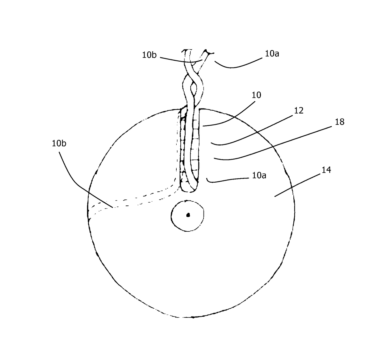
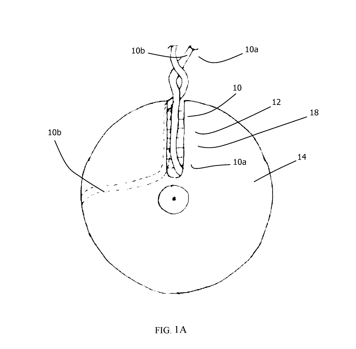
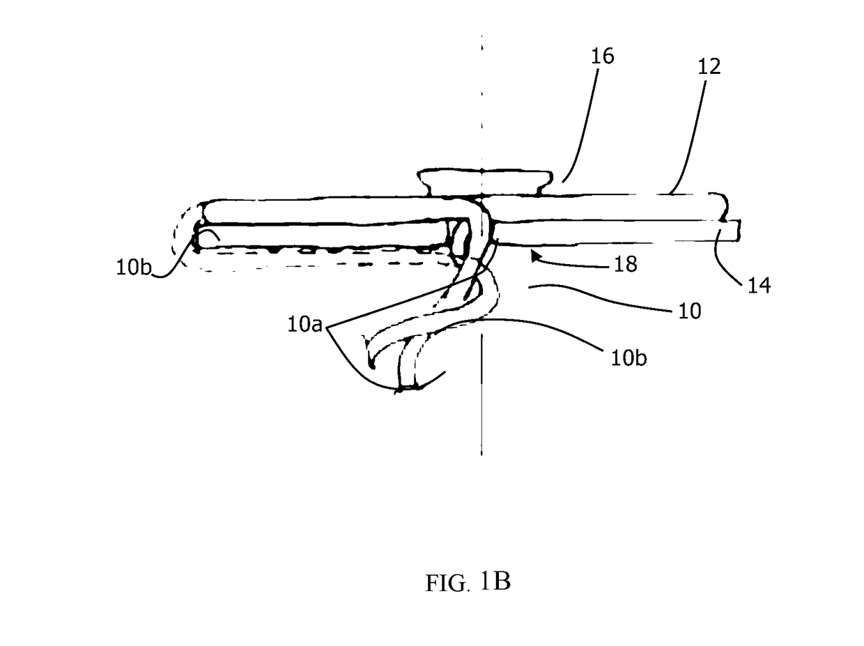
The patent describes a device that allows for non-integer number of turns in a coil without fully completing a full turn. This is achieved by using a planar member, such as a trimming disk, on the back of the magnetic or magnetisable core member to guide the outer end of the wire back to the inner end of the wire. By changing the position in which the outer end of the wire can leave the coil windings, the inductance of the coil can be finely adjusted to achieve the required level. The final part of the last turn occurs behind the core member in the device, where it contributes negligibly to the total coil inductance.

Problems solved by technology

Consequently, each turn represents between about 5% and 6% of the total coil inductance value so it is not normally possible to adjust the inductance value to get within the desired ±1% tolerance level by adjusting the number of complete turns, i.e. adjusting the integer number of turns.
But, as discussed, changing the number of complete turns is much too coarse a method to adjust the coil inductance to within ±1% of the predetermined required inductance value.
In this way, it is possible to provide a non-integer number of turns of the wire 10 on the ferrite core member 14 whilst arranging the inner end 10a and the outer end 10b of the wire 10 to still exit the inductor housing together, but there are several disadvantages with this method, not least the fact that the outer end 10b of the wire 10 along the dashed line path is easily dislodged thereby compromising the inductance value of the coil 12.

Method used


Image

  • Device for enabling a non-integer number of windings to be provided on an inductor
  • Device for enabling a non-integer number of windings to be provided on an inductor
  • Device for enabling a non-integer number of windings to be provided on an inductor

Examples


Embodiment Construction

[0022]The following description is of preferred embodiments by way of example only and without limitation to the combination of features necessary for carrying the invention into effect.

[0023]Reference in this specification to “one embodiment” or “an embodiment” means that a particular feature, structure, or characteristic described in connection with the embodiment is included in at least one embodiment of the invention. The appearances of the phrase “in one embodiment” in various places in the specification are not necessarily all referring to the same embodiment, nor are separate or alternative embodiments mutually exclusive of other embodiments. Moreover, various features are described which may be exhibited by some embodiments and not by others. Similarly, various requirements are described which may be requirements for some embodiments but not other embodiments.

[0024]Referring to FIG. 2, shown is a device 100 for enabling a non-integer number of windings to be provided on an i...


PUM

PropertyMeasurementUnit
magneticaaaaaaaaaa
non-magneticaaaaaaaaaa
electric currentaaaaaaaaaa

Abstract

The invention provides a device for enabling a non-integer number of windings to be provided on an inductor. The device comprises a generally planar member adapted to be positioned adjacent to a magnetic or magnetisable core of an inductor. The member has a wire guide, preferably in the form of a slot, said wire guide comprising a first wire guide portion extending from a peripheral edge of the member towards a central axis thereof, but not reaching said central axis, and including a second wire guide portion which extends from said first wire guide portion to at least partially extend around said central axis. The wire guide enables terminal ends of the inductor coil wire to be brought together to exit the inductor and yet enable a non-integer number of windings to be wound on the magnetic or magnetisable core of the inductor.

Description

[0001]This application claims priority to Chinese patent application No. 201621253662, filed on Nov. 18, 2016, which is hereby incorporated by reference herein in its entirety.FIELD OF THE INVENTION[0002]The invention relates to a device for enabling a non-integer number of windings to be formed on an inductor.BACKGROUND OF THE INVENTION[0003]An inductor, also called a coil or a reactor, is typically a passive two-terminal electrical component which resists changes in electric current passing through it. It consists of a conductor such as a wire usually wound into a number or turns, comprising a coil, around a magnetic or magnetisable core such as a ferrite core. Energy is stored in a magnetic field in the coil as long as current flows through the wire.[0004]In wireless or induction (IPT) power transfer systems, by way of example, the wireless power transfer devices include a magnetic coil as part of the power transmitter (Tx) and / or receiver (Rx) apparatus(es). The Tx / Rx coils form...

Claims


Application Information

Patent Timeline
Patent Type & Authority Applications(United States)
IPC IPC(8): H01F41/06H01F38/14H01F27/28H01F27/24
CPCH01F41/06H01F38/14H01F27/2823H01F27/24H01F5/02H01F27/022H01F27/306H01F27/325
Inventor KRISTOFFERSEN-TUCK, NATASHA LILLIANPAAUWE, MICHAEL VICTOR
Owner APPLE INC
Learn More