Rear Swing Arm Suspension

a swing arm and suspension technology, applied in resilient suspensions, interconnection systems, vehicle components, etc., can solve the problems of long allowed travel distance of shock absorbers, large turning radius of vehicles, inconvenient and uncomfortable driving of vehicles, etc., to improve the comfort of all-terrain vehicles, reduce the width of half-tracks, and reduce turning radius

Active Publication Date: 2018-05-31
ZHEJIANG CFMOTO POWER CO LTD
View PDF14 Cites 4 Cited by
  • Summary
  • Abstract
  • Description
  • Claims
  • Application Information

AI Technical Summary

Benefits of technology

[0005]The present invention is a swing arm type suspension for a rear wheel of an off road vehicle. In one aspect, the tie rods supporting the knuckle for the rear wheel are connected at locations significantly in front of and behind the rotational axis of the rear wheel, so while wheel elevation is primarily controlled by pivoting of the swing arm, toe-in is controlled by the tie rods. In another aspect, the rear end of the swing arm is split between an upper clamping arm and a lower clamping arm defining an eye, with the knuckle connected to the upper and lower clamping arms by joint bearings, and with either the transmission shaft or one of the tie rods extending through the eye of the swing arm to the knuckle. In another aspect, the front of the swing arm is connected to the vehicle frame using a cross-shaft joint, and extension of the suspension significantly decreases half-track width but compression of the suspension does not significantly affect half-track width. Overall, camber, toe in and track width changes are precisely controlled to result in a reduced turning radius for the vehicle while at the same time improving the comfort of the all-terrain vehicle, using a suspension structure which is reasonable in cost, reasonable is size relative to other components of the vehicle, and reasonable in weight contributed to the vehicle.

Problems solved by technology

Such rear swing arm suspensions can lead to a longer permissible travel distance of the shock absorber than traditional suspensions.
However, the structures of such rear swing arm suspensions are complicated and expensive, and also result in a large turning radius of the vehicle, making it inconvenient and uncomfortable to drive the vehicle.

Method used


Image

  • Rear Swing Arm Suspension
  • Rear Swing Arm Suspension
  • Rear Swing Arm Suspension

Examples


Embodiment Construction

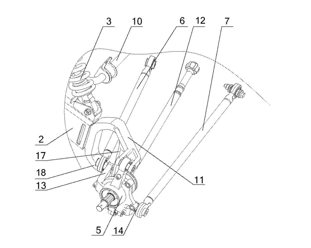
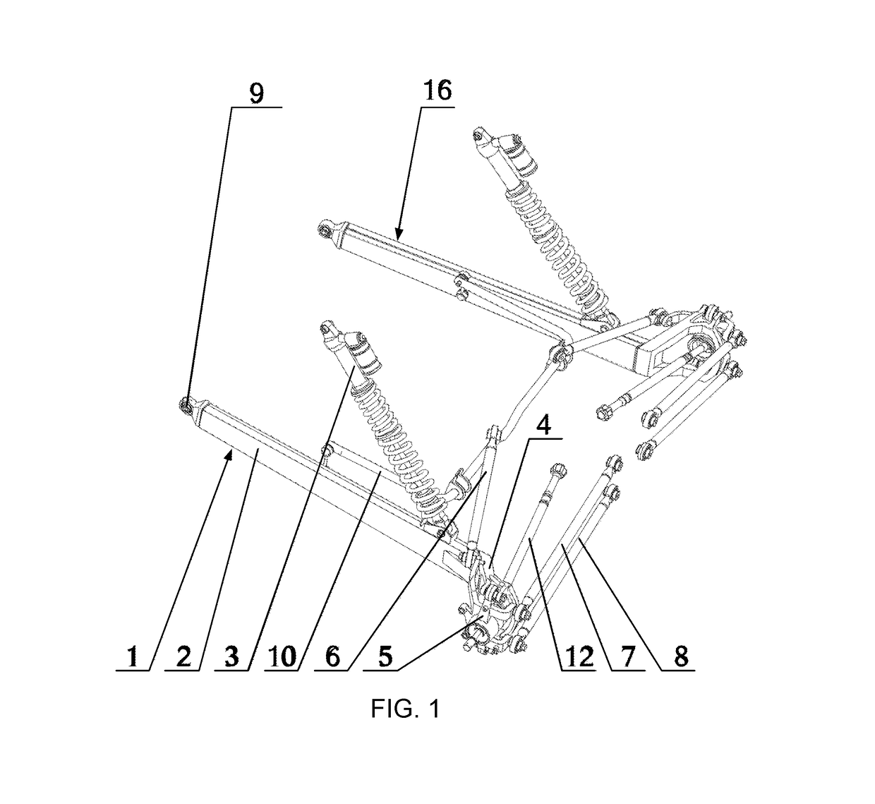
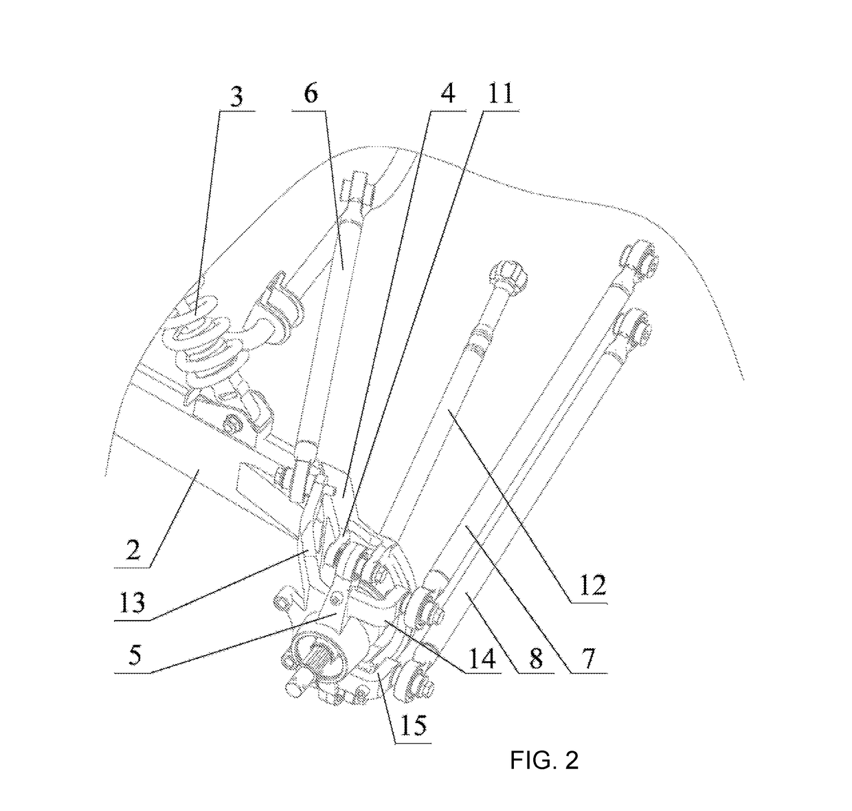
[0032]The rear suspension assembly includes a left rear suspension 1 and a right rear suspension 16, which are preferably symmetrical with respect to each other as well as symmetrically mounted on to the frame of the all-terrain vehicle, utility vehicle, or other similar vehicle intended to be driven off-pavement. The weight of the vehicle is primarily bourn by the swing arm 2, which extends longitudinally on the vehicle between a front attachment joint bearing 9 and a knuckle 5. The joint bearing 9 allows both full pivoting about a substantially horizontal, transversely extending axis as well as a limited amount of pivoting about a substantially vertical axis, so the rearward end of the swing arm can move not only up and down but also inward and outward. As used herein, the term “joint bearing” refers to a joint that allows at least a limited amount of articulated pivoting motion in more than one plane, such as a tie rod end bearing (also known as a helm joint or a rose joint). The...


PUM


Abstract

A swing arm type suspension for a rear wheel of an off road vehicle can use two or three tie rods to control toe-in of the knuckle. The rear end of the swing arm is split between an upper clamping arm and a lower clamping arm defining an eye, with the knuckle connected to the upper and lower clamping arms by joint bearings, and with either the transmission shaft or one of the tie rods extending through the eye of the swing arm to the knuckle. The front of the swing arm can be connected to the vehicle frame using a cross-shaft joint. Camber, toe-in and half-track width are controlled to result in a smaller turning radius with better ride characteristics.

Description

CROSS-REFERENCE TO RELATED U.S. APPLICATION(S)[0001]None.FIELD OF THE INVENTION[0002]The present invention relates to suspension systems in vehicles, and particularly to rear suspensions of the swing arm suspension type, which can be used in offroad vehicles such as UVs and ATVs.BACKGROUND OF THE INVENTION[0003]Utility vehicles (“UVs”) and all terrain vehicles (“ATVs”) are well known for travel over a wide variety of terrains, including over unpaved trails or fields, rocks, etc. Such vehicles are widely used in agriculture and forestry operations, as well as in safety operations such as for rugged mountain crossings. Such vehicles are also widely used for recreational enjoyment in natural, outdoor settings away from pavement. In general, such UVs and ATVs have a lower price point and are considerably smaller and simpler than on-road vehicles such as passenger automobiles and trucks.[0004]One type of rear suspension known for use on UVs and ATVs may be referred to as a swing axle or ...

Claims


Application Information

Patent Timeline
Patent Type & Authority Applications(United States)
IPC IPC(8): B60G3/20B60G7/00B60G21/055
CPCB60G3/202B60G7/008B60G21/055B60G2200/46B60G2200/462B60G2206/50B60G2200/182B60G2204/148B60G2300/07
Inventor HU, XIAYANGFENG, MEILIN
Owner ZHEJIANG CFMOTO POWER CO LTD
Why Eureka
Try Eureka