
Aircraft having a drag compensation device based on a boundary layer ingesting fan

a technology of drag compensation and ingesting fan, which is applied in the direction of propellers, airflow influencers, power plant types, etc., can solve the problems of manufacturing and certifying aircraft, and achieve the effect of reducing the clearance of the tail and increasing the cost of designing

Inactive Publication Date: 2018-05-31
AIRBUS OPERATIONS GMBH
View PDF5 Cites 12 Cited by
  • Summary
  • Abstract
  • Description
  • Claims
  • Application Information

AI Technical Summary

Benefits of technology

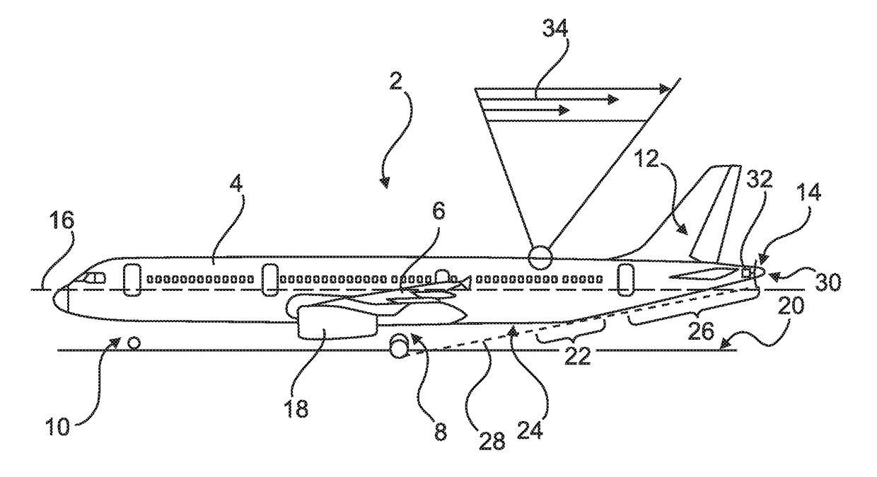
The invention aims to improve the drag behavior of an aircraft without increasing the cost for redesigning and recertification of the aircraft. This is achieved by incorporating a ducted fan at the tail section of the fuselage and proposing an improved design that avoids damaging the ducted fan while maintaining tail clearance for take-off and landing.

Problems solved by technology

This increases the costs for designing, manufacturing and certifying the aircraft.

Method used


Image

  • Aircraft having a drag compensation device based on a boundary layer ingesting fan
  • Aircraft having a drag compensation device based on a boundary layer ingesting fan
  • Aircraft having a drag compensation device based on a boundary layer ingesting fan

Examples


Embodiment Construction

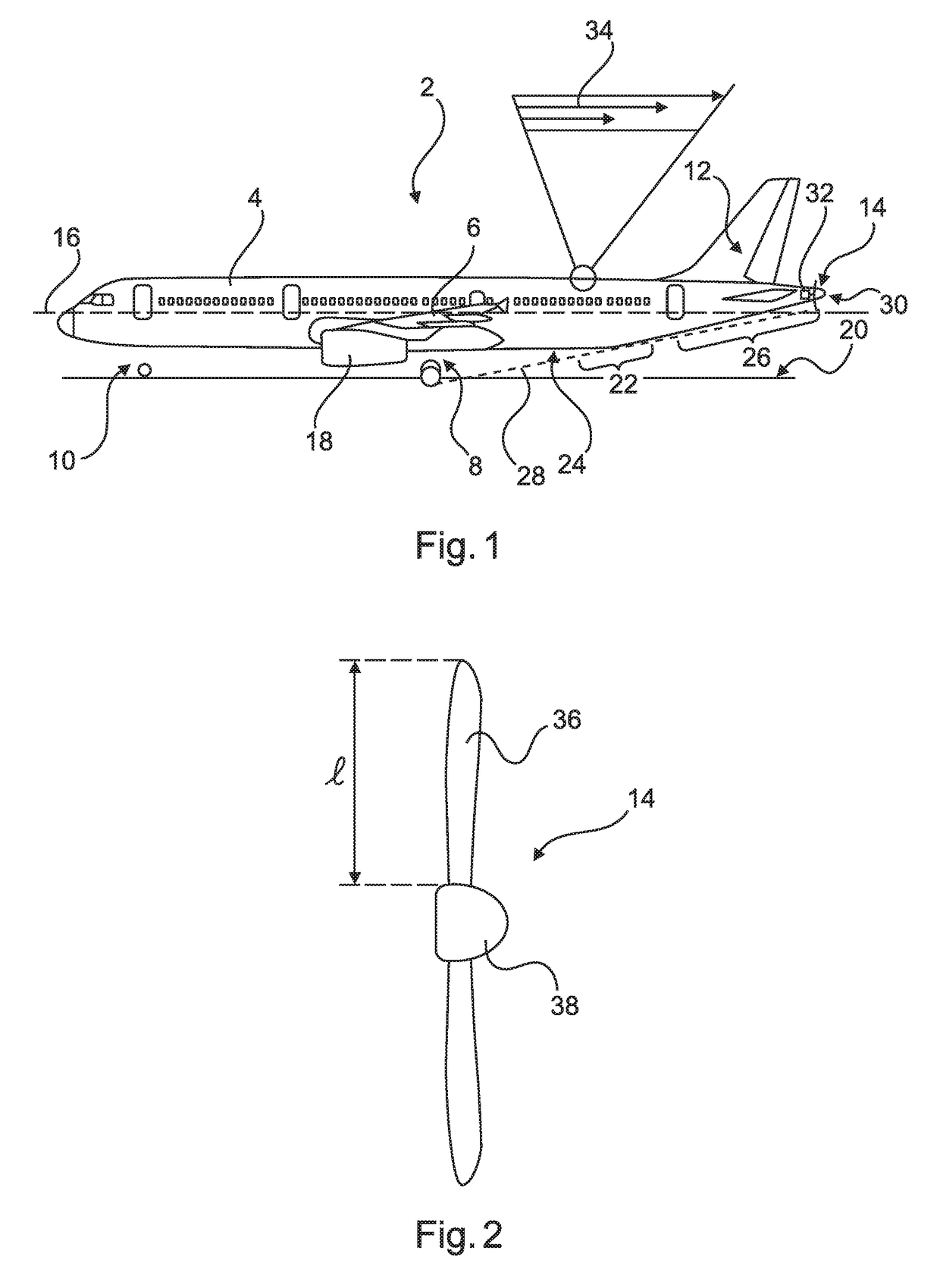
[0030]FIG. 1 shows an aircraft 2 having a fuselage 4, a wing 6, a main landing gear 8, a nose landing gear 10, a tail section 12 and a rear fan 14. The fuselage 4 may consist of one or more central portions having constant cross sections as well as a tapered section at a nose and a tail. The fuselage 4 may be designed as a cylindrical (tubular) fuselage with a main or longitudinal extension axis 16.

[0031]The term “cylindrical” does not necessarily require a circular cross-section, but merely expresses an elongate shape along the longitudinal axis 16 with a cross section that remains unchanged along a major section of the fuselage 4. Commercial aircraft are known having a circular cross-section, while others may tend to be more oval, i.e. having a slightly unequal relationship between height and width of the fuselage. Other commercial aircraft are known having a clearly oval cross-section at least in a certain region. These are not ruled out by the term “cylindrical”.

[0032]The wing 6...


PUM


Abstract

An aircraft includes a fuselage having a tapered rear shape, a landing gear for moving the aircraft on a runway, a wing attached to the fuselage, at least a main engine for providing a main thrust and a rear fan, wherein the rear fan is attached to a tail section of the fuselage, wherein the aircraft is designed for conducting a take-off rotation around the landing gear during take-off from the runway, such that the tail section of the fuselage approaches the runway, wherein the rear fan is an open fan having fan blades extending in a radial direction to a longitudinal axis of the fuselage, wherein the fan blades are dimensioned to equal at least a boundary layer thickness of the flow along the fuselage and to be smaller than the gap between the runway and the tail section of the fuselage during the take-off rotation.

Description

FIELD OF THE INVENTION[0001]The invention relates to an aircraft having a drag compensation device based on a boundary layer ingesting fan.BACKGROUND OF THE INVENTION[0002]An overall efficiency of an aircraft can be improved through a number of different measures. By increasing the efficiency of the propulsion, fuel consumption can be reduced and thus, the efficiency of the aircraft is improved. Further, the reduction of aerodynamic drag is beneficial for reducing the required power for propulsion. The reduction of drag may be accomplished through a variety of active and passive drag reduction means. Passive means may include a modified / optimized design of the flow surfaces of the aircraft in general and may include the introduction of devices, which positively influence the air flow. Active means may include devices for actively influencing a boundary layer of the aerodynamic flow particularly through removing air from the boundary layer in order to maintain laminar flow under cond...

Claims


Application Information

Patent Timeline
Patent Type & Authority Applications(United States)
IPC IPC(8): B64C21/00B64C11/30B64C1/00
CPCB64C21/00B64C11/30B64C1/0009B64C2230/28B64C2230/04B64C23/005B64D27/02B64D27/24Y02T50/10B64C21/01B64D27/026
Inventor TRAHMER, BERND
Owner AIRBUS OPERATIONS GMBH
Learn More