Non-isolated integrated boost DC/AC converter and control method thereof
What is Al technical title?
Al technical title is built by PatSnap Al team. It summarizes the technical point description of the patent document.
A non-isolated and converter technology, applied in the field of non-isolated integrated boost DC/AC converter and its control, can solve the problem of low boost ratio
Active Publication Date: 2021-04-30
合肥名龙电子科技有限公司
View PDF2 Cites 6 Cited by
Summary
Abstract
Description
Claims
Application Information
AI Technical Summary
This helps you quickly interpret patents by identifying the three key elements:
Problems solved by technology
Method used
Benefits of technology
Problems solved by technology
[0007] Aiming at the problem of low boost ratio in the boost inverter in the prior art, the present invention provides a non-isolated integrated boost DC / AC converter
Method used
Image
Click on the blue label to locate the original text in one second.
Reading with bidirectional positioning of images and text.
Examples
Embodiment 1
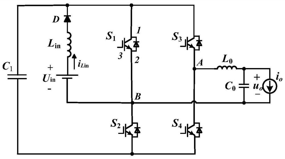
[0043] Such as figure 1 As shown, a non-isolated integrated step-up DC / AC converter of this embodiment includes a power switch tube S 1 , S 2 , S 3 and S 4 , diode D, inductor L in and capacitance C 1 ;
[0044] Inductance L in Connect one end to the input power supply U in One end, the inductance L in The other end is connected to the anode of diode D;
[0045] The cathode of the diode D is connected to the power switch tube S respectively 1 and S 3 Terminal 1, capacitor C 1 One end of the capacitor C 1 The other ends are connected to the power switch tube S 2 and S 4 terminal 2 of
[0046] Input power U in The other end of the power switch tube S 1 Terminal 2, the power switch tube S 2 Terminal 1 of the terminal and one end of the AC side are grounded;
[0047] Power switch tube S 3 Terminal 2 and power switch tube S 4 Terminal 1 is connected to the other end of the AC side;
[0048] Power switch tube S 3 terminal 2 and the power switch S 4 Terminal 1...
Embodiment 2
[0053] Such as figure 1 As shown, a non-isolated integrated step-up DC / AC converter of this embodiment, on the basis of Embodiment 1, the DC side is a DC power supply U in , in the actual application scenario is the output voltage of the photovoltaic panel, and the AC side also includes a filter, the filter is LC type, including a filter inductor Lo and a filter capacitor Co, one end of the filter inductor Lo is connected to node A, and the filter The other end of the inductor Lo and one end of the filter capacitor Co and the grid or load R O One end is connected, the other end of the filter capacitor Co is connected to the grid or load R O The other end is connected to Node B. Filter pair voltage U AB Perform filtering to remove harmonic interference, which can be selected according to the actual application scenario, and can be an LC filter (such as figure 1 As shown), LCL filter, etc., the output of the filter can be connected to the grid or load, and the load character...
PUM
Abstract
The invention discloses a non-isolated integrated boost DC / AC converter and a control method thereof, and belongs to the technical field of power electronic converters. The DC / AC converter comprises power switch tubes S1, S2, S3 and S4, a diode D, an inductor Lin and a capacitor C1. One end of the direct current side of one converter is connected with one end of an inductor Lin, the other end of the inductor Lin is connected with the anode of the diode D, the cathode of the diode D is connected with terminals 1 of a power switch tube S1 and a power switch tube S3 and one end of a capacitor C1, and the other end of the capacitor C1 is connected with terminals 2 of a power switch tube S2 and a power switch tube S4; the other end of the direct current side, the terminal 2 of the power switch tube S1, the terminal 1 of the power switch tube S2 and one end of the alternating current side are all grounded; and the terminal 2 of the power switch tube S3 and the terminal 1 of the power switch tube S4 are connected to the other end of the alternating current side. Aiming at the problem that a traditional boost inverter has leakage current, the boost inverter is high in integration level and small in size, and the problem of leakage current can be effectively solved.
Description
technical field [0001] The invention relates to the technical field of power electronic converters, in particular to a non-isolated integrated step-up DC / AC converter and a control method thereof. Background technique [0002] In the current context of increasingly tense global energy supply, clean, environmentally friendly, and noiseless solar photovoltaic power generation has received widespread attention from countries all over the world. Among them, the inverter is the key interface device in the photovoltaic power generation system. At present, the transformerless non-isolated photovoltaic power generation system has become a research hotspot among scholars due to its small size, light weight, low cost and easy installation. However, the traditional non-isolated inverter lacks the electrical isolation of the transformer. Due to the existence of the parasitic capacitance of the photovoltaic cell to the ground, leakage current is easily generated in the photovoltaic powe...
Claims
Application Information
Patent Timeline
Application Date:The date an application was filed.
Publication Date:The date a patent or application was officially published.
First Publication Date:The earliest publication date of a patent with the same application number.
Issue Date:Publication date of the patent grant document.
PCT Entry Date:The Entry date of PCT National Phase.
Estimated Expiry Date:The statutory expiry date of a patent right according to the Patent Law, and it is the longest term of protection that the patent right can achieve without the termination of the patent right due to other reasons(Term extension factor has been taken into account ).
Invalid Date:Actual expiry date is based on effective date or publication date of legal transaction data of invalid patent.