Surface shape measuring method, misalignment amount calculating method, and surface shape measuring device

Active Publication Date: 2018-05-31
TOKYO SEIMITSU
View PDF0 Cites 11 Cited by
  • Summary
  • Abstract
  • Description
  • Claims
  • Application Information

AI Technical Summary

Benefits of technology

[0033]According to the present invention, it is possible to measure a surface shape of a workpiece wi

Problems solved by technology

Therefore, when an imperfectly circular object is measured, the true value (diameter) cannot be obtained by the measurement and this may cause a large measurement error.
In particular, when the workpiece has low roundness, the measurement results tend to vary depending on the direction in which the diameter of the workpiece is measured (the position at which the probe is brought into contact with the workpiece), and it is difficult to measure the diameter of the workpiece with high precision and high reproducibility.
Thus, the method disclosed in PTL 1 is poor in versatility.
Moreover, in the misalignment amou

Method used


Image

  • Surface shape measuring method, misalignment amount calculating method, and surface shape measuring device
  • Surface shape measuring method, misalignment amount calculating method, and surface shape measuring device
  • Surface shape measuring method, misalignment amount calculating method, and surface shape measuring device

Examples


first embodiment

[0062]First, a first embodiment is described.

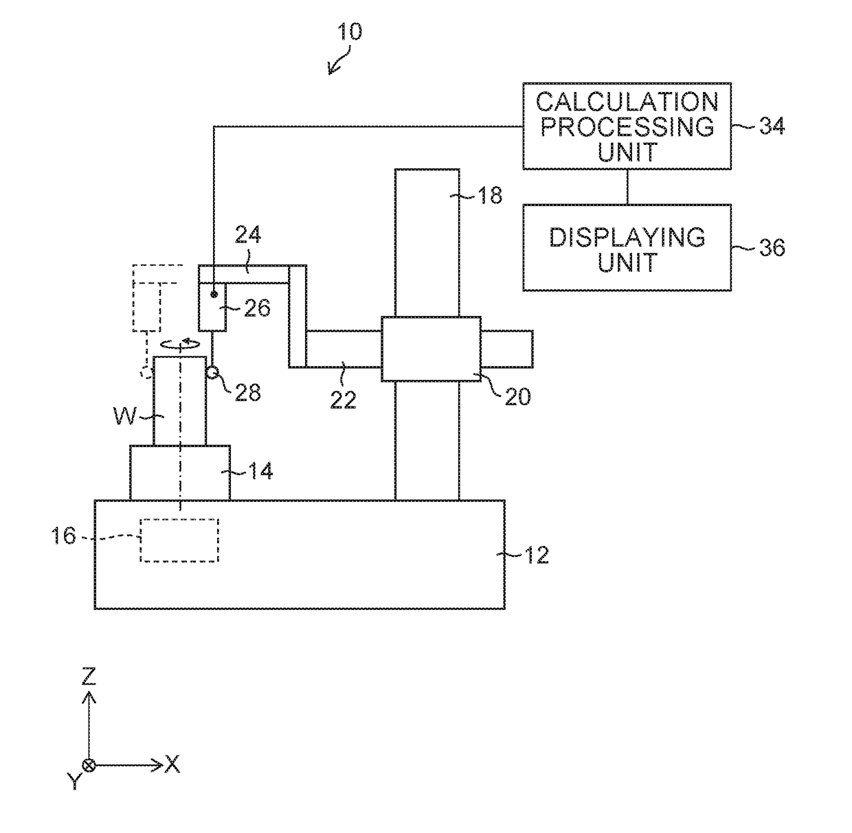
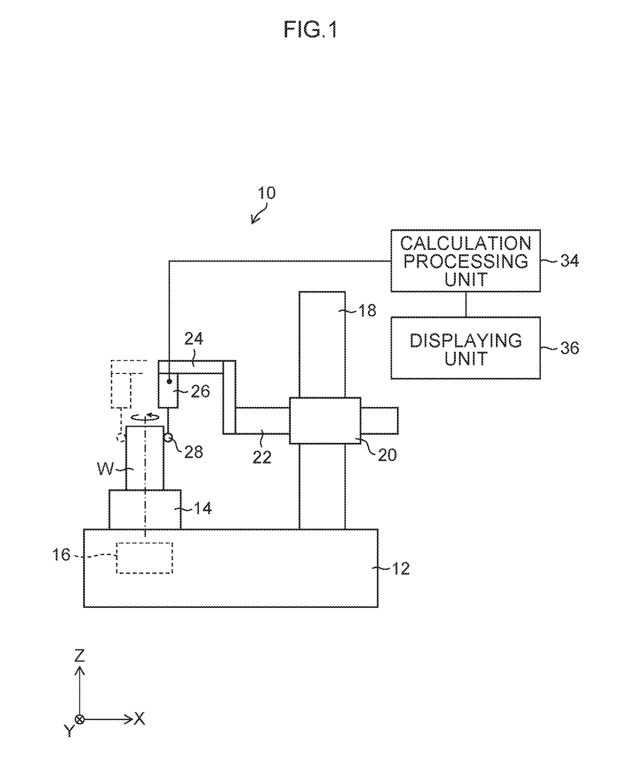
[0063]FIG. 1 is a schematic diagram showing a roundness measuring device 10 according to the first embodiment. As shown in FIG. 1, the roundness measuring device 10 according to the first embodiment includes a rotary table (turn table) 14 on which a workpiece (measuring object) W is placed on a main body base (base stage) 12. The rotary table 14 is configured to be finely fed (inched) in an X-direction and in a Y-direction with an X-direction fine movement knob (not shown) and a Y-direction fine movement knob (not shown). The inclination of the rotary table 14 is adjusted in the X-direction and in the Y-direction with an X-direction inclining knob (not shown) and a Y-direction inclining knob (not shown).

[0064]Note that the X-direction, the Y-direction and a Z-direction are directions perpendicular to each other, the X-direction is a horizontal direction (corresponding to the movement direction of an arm 22 mentioned later), the Y-directio...

second embodiment

[0114]Next, the second embodiment is described. Note that description is made again throughout its entirety although there are portions overlapping with those in the aforementioned first embodiment.

[0115]FIG. 7 is a schematic diagram showing a configuration of the roundness measuring device 100 according to the second embodiment.

[0116]As shown in FIG. 7, the roundness measuring device 100 according to the second embodiment includes a rotary table (rotary table) 114 on which a workpiece (measuring object) W is placed on a main body base (base stage) 112. The rotary table 114 is configured to be finely fed (inched) in the X-direction and the Y-direction with an X-direction fine movement knob (not shown) and a Y-direction fine movement knob (not shown). The inclination of the rotary table 114 is adjusted in the X-direction and the Y-direction with an X-direction inclining knob (not shown) and a Y-direction inclining knob (not shown).

[0117]Note that the X-direction, the Y-direction and ...


PUM


Abstract

There are provided a surface shape measuring method and a surface shape measuring device which can measure the diameter of a workpiece to be measured with high precision and high reproducibility and have excellent versatility. These method include: acquiring first shape data indicating a surface shape of the workpiece with a detector being disposed on one side across a workpiece while rotating the workpiece relatively to the detector around a rotational center; acquiring second shape data indicating the surface shape of the workpiece with the detector being disposed on the other side across the workpiece while rotating the workpiece relatively to the detector around the rotational center; and calculating a shape parameter defining the surface shape of the workpiece by collating the first shape data and second shape data. In calculating the shape parameter, a deviation of the detector from the reference line is calculated based on the collation result.

Description

CROSS-REFERENCE TO RELATED APPLICATIONS[0001]This application is a Continuation of PCT International Application No. PCT / JP2016 / 069917 filed on Jul. 5, 2016, which claims priorities under 35 U.S.C. §119(a) to Japanese Patent Application No. 2015-167972 filed on Aug. 27, 2015, Japanese Patent Application No. 2016-052678 filed on Mar. 16, 2016 and Japanese Patent Application No. 2016-071002 filed on Mar. 31, 2016. Each of the above application(s) is hereby expressly incorporated by reference, in its entirety, into the present application.BACKGROUND OF THE INVENTIONField of the Invention[0002]The present invention relates to a technology of measuring a surface shape of a workpiece by detecting a displacement of a surface of the workpiece by a detector while relatively rotating the workpiece and the detector around a rotational center.Description of the Related Art[0003]Conventionally, as a surface shape measuring device which measures a surface shape of a workpiece (object to be measur...

Claims


Application Information

Patent Timeline
IPC IPC(8): G01B3/22G01B5/08G01B5/20
CPCG01B5/10G01B5/08G01B5/20G01B3/22G01B5/201
Inventor MASUTA, HIKARU
Owner TOKYO SEIMITSU
Why Eureka
Try Eureka