Radio frequency front-end circuit and communication device

Active Publication Date: 2018-05-31
MURATA MFG CO LTD
View PDF3 Cites 9 Cited by
  • Summary
  • Abstract
  • Description
  • Claims
  • Application Information

AI Technical Summary

Benefits of technology

[0037]With the features described above, the communication device is able to be applied to a larger number of bands while the attenuation characteristics and the bandpass characteristics

Problems solved by technology

With the related-art described above, however, when radio frequency signals in multiple bands are transmitted and/or received at the same time or substantially the same time as in the CA, the radio frequency signal in one band not only passes through a filter including a pass band corresponding to the relevant one band, but also leaks to another filter.
This leads to degradation of attenuation characteristics in the othe

Method used


Image

  • Radio frequency front-end circuit and communication device
  • Radio frequency front-end circuit and communication device
  • Radio frequency front-end circuit and communication device

Examples


embodiment example (

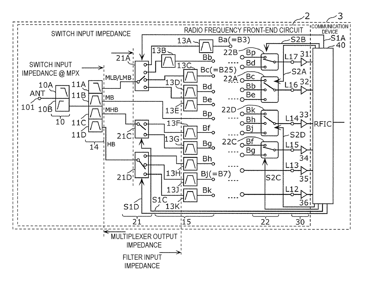
[0163namely, of the filter in the posterior stage in which a resonator at the start position is a serial arm resonator). More specifically, FIG. 7 represents an input impedance of the filter 13C (Bc, also denoted by B25).

[0164]As illustrated in FIG. 7, since the filter 13C is the acoustic wave filter, the input impedance of the filter 13C at frequencies outside the pass band (about 1850 MHz to about 1915 MHz) thereof is substantially capacitive. Thus, the input impedance of the filter 13C is capacitive, specifically capacitive in a region closer to OPEN, at frequencies outside the pass band of one (MLB / LMB filter 11A) of the filters in the initial stage, the one being connected to the filter 13C by the switch circuit 21. Stated in another way, in the Preferred Embodiment Example, an impedance at the output terminal of the filter in the initial stage (e.g., at the other terminal of the first acoustic wave filter) and an impedance at the input terminal of the filter in the posterior s...


PUM


Abstract

A radio frequency front-end circuit includes a multiplexer including filters with different pass bands and including a first acoustic wave filter and a first terminal of each of the filters being connected in common, a second acoustic wave filter including a pass band within the pass band of the first acoustic wave filter, and a switch including a common terminal connected to a second terminal of the first acoustic wave filter and selective terminals including a selective terminal connected to the second acoustic wave filter. Each of an acoustic wave resonator of the first acoustic wave filter located closest to the switch and an acoustic wave resonator of the second acoustic wave filter located closest to the switch, is a serial arm resonator.

Description

CROSS REFERENCE TO RELATED APPLICATIONS[0001]This application claims the benefit of priority to Japanese Patent Application No. 2016-229576 filed on Nov. 25, 2016 and Japanese Patent Application No. 2017-177224 filed on Sep. 15, 2017. The entire contents of these applications are hereby incorporated herein by reference.BACKGROUND OF THE INVENTION1. Field of the Invention[0002]The present invention relates to a radio frequency front-end circuit including a multiplexer, and also relates to a communication device.2. Description of the Related Art[0003]Recently, communication devices, for example, cellular phones, have been desired to operate in a multiband mode in which the device is adaptable for a plurality of frequency bands (also simply called “bands”) with one terminal. According to this a trend, radio frequency front-end circuits, for example, front-end modules, incorporated in the communication devices have also been desired to operate in the multiband mode. Such a radio frequen...

Claims


Application Information

Patent Timeline
IPC IPC(8): H03H9/72H03H9/70H03H9/58
CPCH03H9/725H03H9/706H03H9/58H03H9/70H03H9/703H03H9/72H04B1/0057H04B1/006H04B1/40H04B1/005
Inventor TAKEUCHI, MORIO
Owner MURATA MFG CO LTD
Why Eureka
Try Eureka