
Mold assembly, method for producing insert molded article, and insert molded article

a technology of insert molded article and mold assembly, which is applied in the direction of coatings, etc., can solve the problems of increased molding cycle time, decreased productivity, and effort for molding, and achieve the effect of shortening the molding cycle time and increasing productivity

Active Publication Date: 2018-06-07
KK TOKAI RIKA DENKI SEISAKUSHO
View PDF5 Cites 0 Cited by
  • Summary
  • Abstract
  • Description
  • Claims
  • Application Information

AI Technical Summary

Benefits of technology

The invention provides a mold assembly and method for making an insert molded article that can achieve shorter molding cycle time and increased productivity. This is because the need for an inner core is eliminated, which means less work and faster production.

Problems solved by technology

This requires much effort for molding and leads to increased molding cycle time.
As a result, one problem is that the productivity is decreased.

Method used


Image

  • Mold assembly, method for producing insert molded article, and insert molded article
  • Mold assembly, method for producing insert molded article, and insert molded article
  • Mold assembly, method for producing insert molded article, and insert molded article

Examples


Embodiment Construction

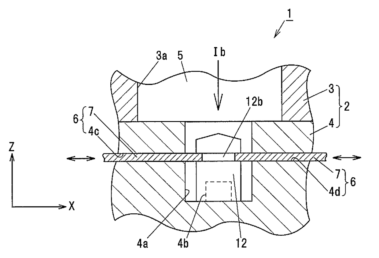
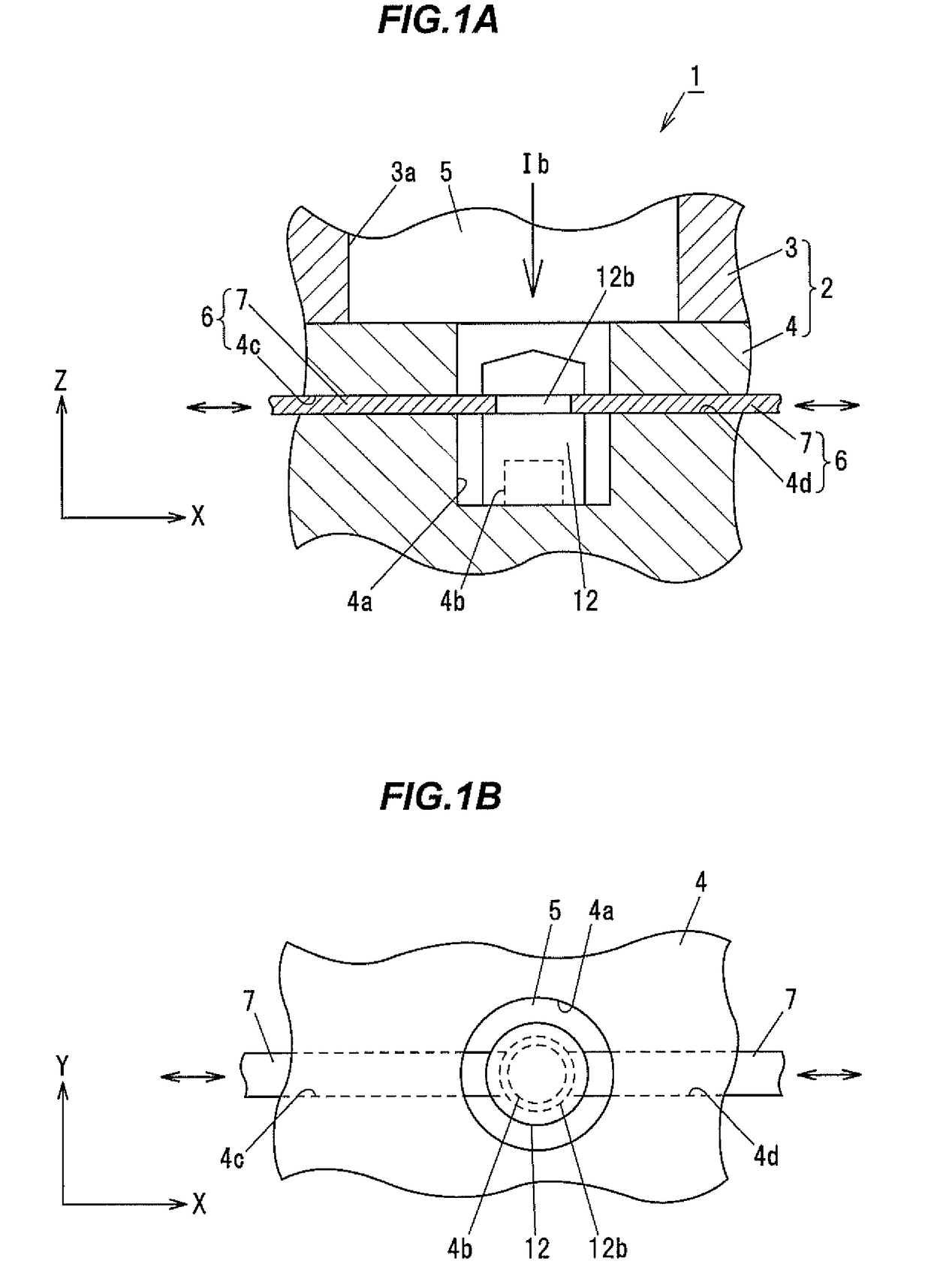
[0021]Embodiments of the invention will be described hereinafter with reference to the appended drawings. In the description below, provided that any point in the mold is taken as the origin, the Z-axis is defined as an axis extending along the opening and closing direction of the mold, the X-axis is defined as an axis extending in a direction orthogonal to the Z-axis, and the Y-axis is defined as an axis extending in a direction orthogonal to the Z-axis and the X-axis.

[0022]Furthermore, provided that a Cartesian coordinate system with the X-, Y-, Z-axes is defined on the mold, X direction is defined as a direction along the X-axis, Y direction is defined as a direction along the Y-axis, Z direction is defined as a direction along the Z-axis, and XV direction is defined as any direction in the plane including the X-axis and the Y-axis (XY plane). In the description below, the X direction, the Y direction, and the XY direction are also referred to as radial directions.

[0023]A mold as...


PUM

PropertyMeasurementUnit
moldingaaaaaaaaaa
molding cycle timeaaaaaaaaaa
cycle timeaaaaaaaaaa

Abstract

A mold assembly includes a mold body configured to mold an insert molded article, and a support member including at least two support pieces configured to support an insert part in a direction substantially orthogonal to a mold opening and closing direction. The insert part is disposable within the mold body, the support pieces are each configured to be movable between a supporting position and a non-supporting position, and the support pieces are each configured to support the insert part at the supporting position, and not to support the insert part at the non-supporting position.

Description

[0001]The present application is based on Japanese patent application No. 2016-235874 filed on Dec. 5, 2016, the entire contents of which are incorporated herein by reference.BACKGROUNDTechnical Field[0002]The present invention relates to a mold assembly, a method for producing an insert molded article, and an insert molded article.Related Art[0003]Among mold assemblies in the related art, there are known mold assemblies for use in insert molding (see, for example, JP H09-300385A).[0004]The mold assembly disclosed in JP H09-300385A is configured so that a plurality of cores can be mounted in the mold. The cores are slidably movable in the direction a molded article is removed. The cores each have a fitting hole into which a fitting pin can be detachably attached in a direction different from the direction the molded article is removed. The fitting pin is formed on each of support members that support the molded article.[0005]The molded article, in which an insert member is inserted ...

Claims


Application Information

Patent Timeline
Patent Type & Authority Applications(United States)
IPC IPC(8): B29C45/14
CPCB29C45/14073B29C45/14065B29C2045/14122
Inventor MANO, SHOHEI
Owner KK TOKAI RIKA DENKI SEISAKUSHO
Learn More