Electric parking brake actuator for actuation of a parking brake in a motor vehicle

a technology for parking brakes and actuators, which is applied in the direction of braking systems, gearing control, belts/chains/gearrings, etc., can solve the problems of high cost, large installation space, and complex construction of the actuating device, and achieve economic and readily commercially available, low cost, and favorable energy balance

Active Publication Date: 2018-06-07
FTE AUTOMOTIVE GMBH & CO KG
View PDF4 Cites 24 Cited by
  • Summary
  • Abstract
  • Description
  • Claims
  • Application Information

AI Technical Summary

Benefits of technology

[0019]In principle it is possible to provide, as a locking device, a small spring-biased hydraulic piston-cylinder arrangement with a piston rod co-operating with the stop surface of the blocking disc or also only a pin which is spring-biased in direction of the profile at the blocking disc and which can be drawn away from the profile by way of a pull cable or the like in order to free the stop surface of the profile. However, with respect to, in particular, low costs and notional use of the parking brake actuator in a motor vehicle with at least in part an electric drive it is preferred if the locking device is a solenoid with an axially movable plunger which is surrounded by a coil fixed relative to the housing. The plunger has a contact end opposite the profile of the blocking disc and is biased by a biasing spring in the direction of the profile, in which case the contact end in a de-energized state of the coil bears against the profile so that it is capable of coming into engagement with the stop surface of the profile and in an energized state of the coil is drawn against the force of the biasing spring away from the profile so as to free the stop surface of the profile. Solenoids of that kind are economically and readily commercially available and have a favorable energy balance, since the electric control of the solenoid always takes place only very briefly, in particular when in secondary alternate operation of the parking brake actuator the stop surface of the blocking disc is to be freed so as to allow rotation, under the effective force of the spring element at the actuating rod, of the blocking disc in the second direction of rotation and thus axial displacement of the actuating rod into the blocking position. A further advantage of use of a solenoid lies in the fact that the inductance of the coil can be detected by an electronic system so as to determine the position of the plunger. Thus, positional information with respect to the locking device—locking or releasing the blocking disc can be obtained in simple mode and manner.
[0020]Advantageously, the housing of the parking brake actuator can in addition be provided integrally with a flange for securing to a transmission housing having a central opening through which the actuating rod, which carries the actuating element, and the spring element extend outwardly. The parking brake actuator can thus be externally flange-mounted in simple manner on the transmission housing. Separate mounting of components of the parking brake actuator in the transmission housing is not required.
[0021]The parking brake actuator in accordance with one aspect of the invention provides a small need for installation space as well as the possibility of simple mounting and connection of a parking brake actuator, which is preassembled and provided as a subassembly, at a transmission. It is also preferred if an electronic module is integrated in the housing of the parking brake actuator, which has at least one electronic system required for activation of the electric motor and an interface module for electrical contact-making with the parking brake actuator. The transmission mechanism can be separated in the housing from the electronic module by an intermediate cover which in turn is sealed off relative to the environment by an outer cover secured to the housing. Advantageously the intermediate cover can then also mount a bearing in the housing (double function of the intermediate cover), which in turn rotatably mounts a part of the transmission mechanism, for example the afore-mentioned crank arm, with low friction relative to the housing.
[0022]Finally, a sensor arrangement for positional detection of the actuating rod can also be integrated in the housing of the parking brake actuator advantageously in protected manner. The sensor arrangement includes a sensor element, which is provided in the electronic module, and a signal element, which in the region of the eccentric coupling of the actuating rod to the crank arm is connected with the actuating rod or the crank arm and detectable by the sensor element through the intermediate cover so as to detect at least the unblocking position and the blocking position of the actuating rod, in a given case also its stroke movement therebetween. This measure is also particularly conducive to a small installation space need of the parking brake actuator.

Problems solved by technology

Parking brakes are needed particularly when a self-locking effect of the drive motor for positionally fixing the motor vehicle cannot be used.
A disadvantage of this prior art is evident in the comparatively complex construction of the actuating device.
In addition, a need for a large amount of installation space arises due to the number of additional components of the secondary alternate actuating unit and the relative position thereof necessary for the function.
Finally, the required reverse operation of the electric motor also causes extra cost.

Method used


Image

  • Electric parking brake actuator for actuation of a parking brake in a motor vehicle
  • Electric parking brake actuator for actuation of a parking brake in a motor vehicle
  • Electric parking brake actuator for actuation of a parking brake in a motor vehicle

Examples


Embodiment Construction

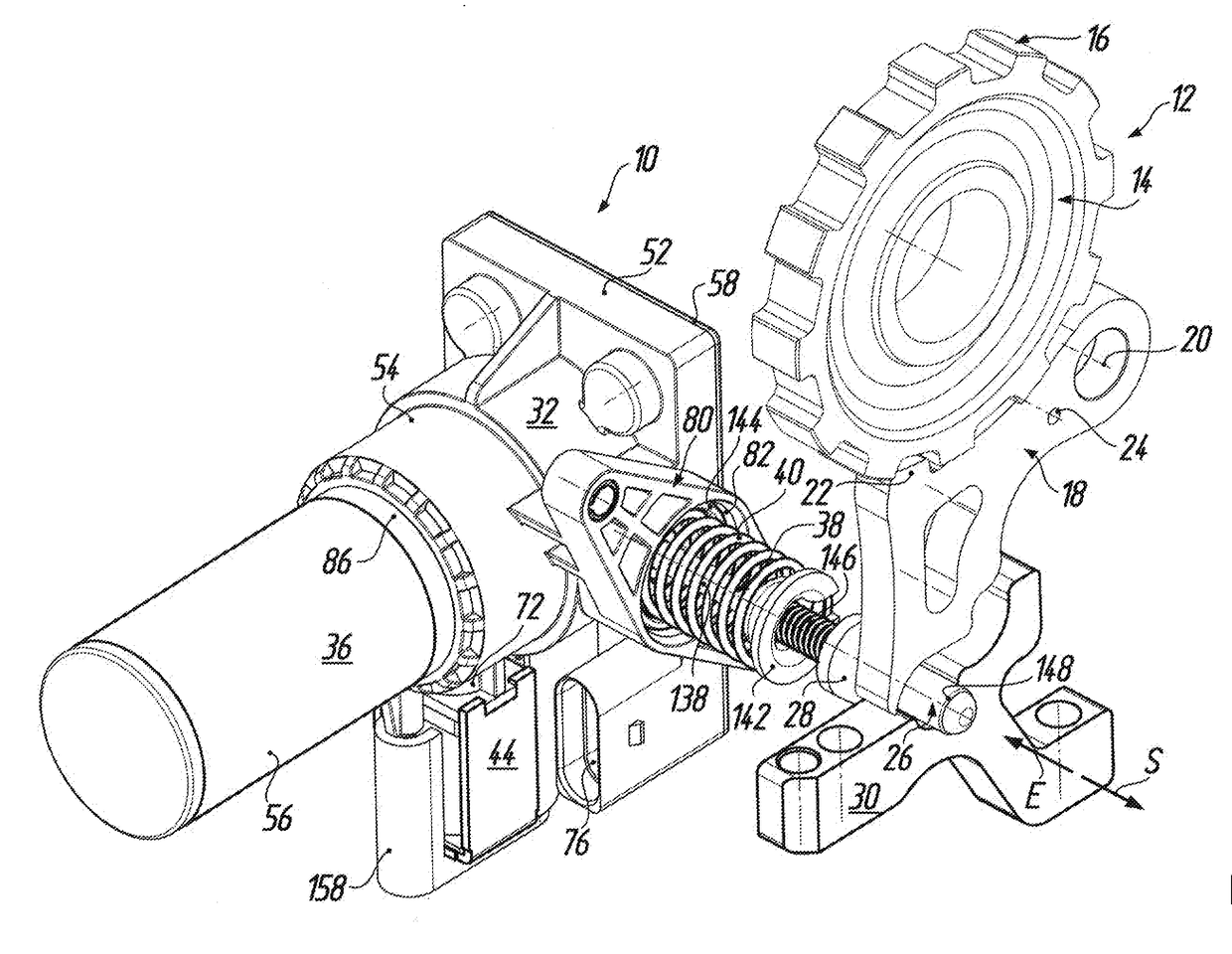
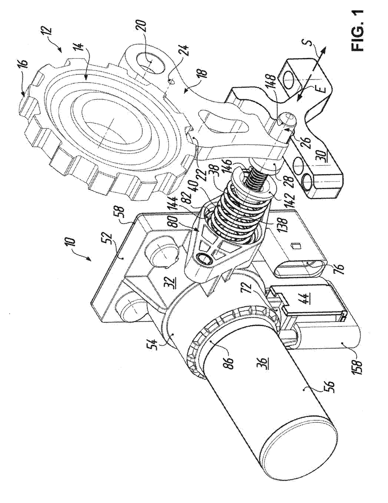
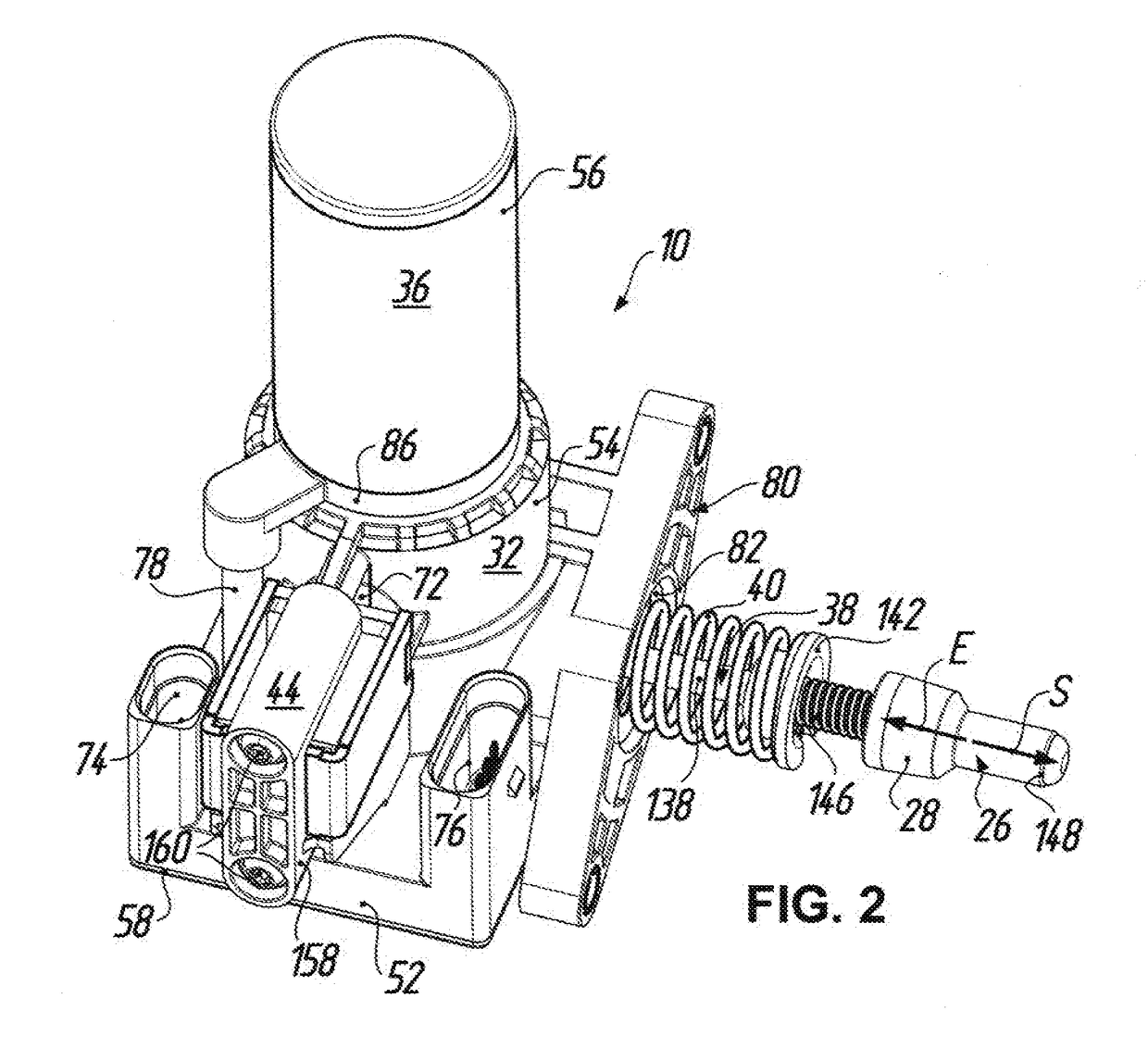
[0041]An electric-brake actuator for actuation of a parking brake 12 in a motor vehicle is denoted in the figures by the reference numeral 10. According to FIG. 1 the parking brake 12 includes, in a manner known per se, a parking brake wheel 14 which is arranged on a transmission shaft (not illustrated) of a motor vehicle transmission to be fixed rotationally and axially relative thereto and has a toothing 16 at the outer circumference. For mechanically positive locking of the drive train of the motor vehicle the parking brake 12 further includes a pawl 18, which is coupled to a transmission housing (not shown here) to be pivotable about a pivot axis 20 and which has a locking tooth 22 which when the pawl 18 is pivoted about the pivot axis 20 is capable of mechanically positive engagement with the toothing 16 of the parking brake wheel 14. The reference numeral 24 indicates a bore in the pawl 18, at which bore a return spring (not shown here) supported relative to the transmission h...


PUM


Abstract

An electric parking brake actuator has a transmission mechanism, which is rotationally drivable by an electric motor and converts rotational movement into an axial movement of an actuating rod that carries an actuating element for the parking brake. The actuating rod normally moves by electric motor displacement via the transmission mechanism from an unblocking position to a blocking position and vice versa. A blocking mechanism serves the purpose of holding the actuating rod in the unblocking position of the actuating rod against the force of a spring element. A blocking disc, which is in drive connection with the transmission mechanism, has a stop surface for a locking device in only one rotational direction of the blocking disc. For secondary alternate operation the stop surface is releasable by the locking device so that the actuating rod is biased by the spring element to the blocking position without electric-motorized assistance.

Description

TECHNICAL FIELD[0001]The present invention relates to an electric parking brake actuator for actuation of a parking brake in a motor vehicle. In particular, the invention refers to an electric parking brake actuator that is widely used in recent times in the automobile industry in motor vehicles with electrical drive axles, hybrid gearboxes and modern gearboxes with automatic transmissions.PRIOR ART[0002]Parking brakes are needed particularly when a self-locking effect of the drive motor for positionally fixing the motor vehicle cannot be used. Blocking of the drive train is then usually by way of a parking brake wheel, which is arranged on an output shaft of the gearbox to be secure against relative rotation and has a toothing and which can be mechanically positively locked at the toothing by a parking brake pawl pivotably mounted on a parallel axle, in which case the parking brake pawl has to be pivoted against the force of a return spring biasing the parking brake pawl away from ...

Claims


Application Information

Patent Timeline
Patent Type & Authority Applications(United States)
IPC IPC(8): B60T13/74F16D65/14
CPCB60T13/746F16D65/14B60T13/743F16D2121/24F16D2125/48F16D2127/06F16H61/32F16H63/3441F16H63/3466F16H63/3491F16H63/3425F16H63/3475F16H63/3483F16H63/34F16H63/3416B60T13/741F16H61/16F16H61/682F16H2063/3056
Inventor HEUBNER, WILHELMLENKE, SONJAEBERT, KATRIN
Owner FTE AUTOMOTIVE GMBH & CO KG
Why Eureka
Try Eureka