Vehicle control apparatus and vehicle control method

a technology of vehicle control and control apparatus, which is applied in the direction of scene recognition, instruments, and reradiation, etc., can solve the problems of unnecessary operation of collision avoidance control

Active Publication Date: 2018-06-14
DENSO CORP
View PDF0 Cites 20 Cited by
  • Summary
  • Abstract
  • Description
  • Claims
  • Application Information

AI Technical Summary

Benefits of technology

[0010]In addition, at the overlap ratio equal to or greater than the threshold at which the operation timing for the collision avoidance control is not easily affected by error in the object width, the object width is not changed. As a result, the setting of the operation timing based on the overlap ratio is prioritized. Consequently, the effects that an error in the object width has on the operation timing for the collision avoidance control can be suppressed. The collision avoidance control can be performed at an appropriate timing.

Problems solved by technology

The change in the operation timing for the collision avoidance control may result in an unnecessary operation of the collision avoidance control.

Method used


Image

  • Vehicle control apparatus and vehicle control method
  • Vehicle control apparatus and vehicle control method
  • Vehicle control apparatus and vehicle control method

Examples


first embodiment

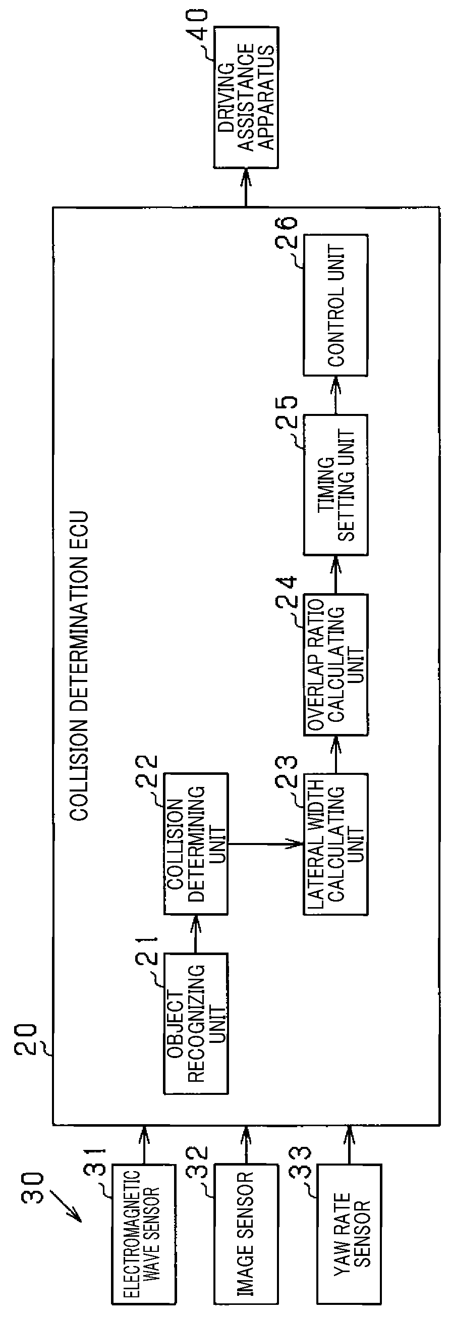
[0028]A system 100 shown in FIG. 1 is mounted in a vehicle CS. The system 100 detects an object that is positioned ahead of the own vehicle CS. When a risk of collision between the object and the own vehicle CS is present, the system 100 performs an operation to avoid or mitigate the collision between the own vehicle CS and the object. According to the present embodiment, the system 100 includes various sensors 30, an electronic control unit (ECU) 20, and a driving assistance apparatus 40. The ECU 20 functions as the vehicle control apparatus.

[0029]The various sensors 30 are connected to the ECU 20. The various sensors 30 output detection results regarding objects to the ECU 20. In FIG. 1, the various sensors 30 include an electromagnetic wave sensor 31, an image sensor 32, and a yaw rate sensor 33. The image sensor 32 acquires a captured image. The yaw rate sensor 33 detects movement of the own vehicle CS in a lateral direction. In cases in which distinction is made between an obje...

second embodiment

[0077]Configurations according to a second embodiment that differ from those according to the first embodiment will mainly be described. According to the second embodiment, the ECU 20 reduces a speed of increase in the reduction ratio from the initial object width WO based on the increase in the number of consecutive same-object determinations N as the lap ratio RR decreases.

[0078]First, the correction coefficient Co according to the second embodiment will be described with reference to FIG. 9. FIG. 9 shows a graph in which a horizontal axis indicates a width coefficient index In_w and a vertical axis indicates the correction coefficient Co. According to the present embodiment, a map that prescribes the relationship between the width coefficient index In_w and the correction coefficient Co shown in FIG. 9 is recorded in the ECU 20. The ECU 20 calculates the correction coefficient Co on the map by changing the width coefficient index In w based on the lap ratio RR.

[0079]The width coe...

third embodiment

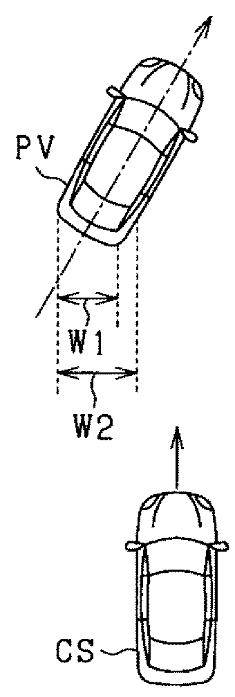
[0091]Configurations according to a third embodiment that differ from those according to the second embodiment will mainly be described. According to the third embodiment, when a determination is made that a state is such that the distance in the lateral direction (vehicle width direction) from the own vehicle CS to the preceding vehicle PV increases, the object width W is reduced compared to that when the state is not such that the distance in the lateral direction from the own vehicle CS to the preceding vehicle PV increases. Here, the state in which the distance in the lateral direction from the own vehicle CS to the preceding vehicle PV increases includes cases in which the preceding vehicle PV is moving away from the own vehicle CS in the lateral direction and cases in which the own vehicle CS is moving away from the preceding vehicle PV in the lateral direction.

[0092]FIG. 12 is a flowchart for explaining a process performed by the ECU 20 according to the third embodiment. The ...


PUM


Abstract

When a likelihood of a collision between an object and an own vehicle is determined to be present, an vehicle control apparatus calculates an object width indicating a size of the object in a lateral direction and an overlap ratio indicating a proportion of an amount of overlap in the lateral direction between the calculated object width and a determination area that is virtually set ahead of the own vehicle. Based on the calculated overlap ratio, an operation timing for a collision avoidance control is set. The object width is changed when the overlap ratio is less than a predetermined threshold such that the object width is less than the object width when the overlap ratio is greater than the predetermined threshold. The operation timing for the collision avoidance control is set based on a new overlap ratio calculated based on the determination area and the object width after change.

Description

CROSS-REFERENCE TO RELATED APPLICATION[0001]This application is based on and claims the benefit of priority from Japanese Patent Application No, 2016-242667, filed Dec. 14, 2016. The entire disclosure of the above application is incorporated herein by reference.BACKGROUNDTechnical Field[0002]The present disclosure relates to a vehicle control apparatus and a vehicle control method.Related Art[0003]Conventionally, a vehicle control apparatus that calculates an overlap ratio in a lateral direction between an own vehicle and an object ahead of the own vehicle is known. The vehicle control apparatus sets an operation timing for collision avoidance control that is performed to avoid a collision between the object and the own vehicle, based on the overlap ratio. The overlap ratio is an index value that is used to determine a risk of collision between the own vehicle and an object that is positioned ahead of the own vehicle. For example, the vehicle control apparatus calculates an object w...

Claims


Application Information

Patent Timeline
Patent Type & Authority Applications(United States)
IPC IPC(8): B60W30/09G08G1/16G01S13/93B60W10/18B60W50/14G06K9/00G01S13/931
CPCB60W30/09G08G1/166G01S13/931B60W10/18B60W50/14G06K9/00805B60W2050/143B60W2420/42B60W2420/52G01S7/41G01S13/867B60W30/0956B60W2420/50G01S2013/93185B60W2554/00G06V20/58
Inventor TAKAKI, RYO
Owner DENSO CORP
Why Eureka
Try Eureka