Illuminated ventilation ring for a uv-light water sanitizer

Active Publication Date: 2018-06-14
CUSTOM MOLDED PROD
View PDF1 Cites 0 Cited by
  • Summary
  • Abstract
  • Description
  • Claims
  • Application Information

AI Technical Summary

Benefits of technology

The present invention is a UV-light sanitization apparatus that has a ventilation ring incorporated into its housing to protect the electronics from moisture while still allowing heated air to exhaust. The ventilation ring is located on top of the housing and has flanges with openings that allow heat to escape while preventing moisture from entering. The openings in the ventilation ring flanges create a window that allows a user to see whether the UV lamp is working. The invention also involves a mounting nut that is made transparent or translucent to better illuminate the clear or translucent ventilation ring and to determine whether the UV lamp is functioning. The mounting nut is permanently affixed to the quartz tube using adhesive to create a water-tight bond. Overall, the invention improves the protection and performance of the UV-light sanitization apparatus.

Problems solved by technology

A problem with ballasts is that they can generate a substantial amount of heat that can damage the apparatus and, because these units are often situated outdoors, the ballast and electronics must be protected from outdoor moisture too.
Two types of designs are typically used to protect these units from moisture and heat but they are problematic.
There are various disadvantages to locating the ballast in an inline external housing however, so a second more common design includes the ballast and electronics placed together with the other components in a unitary but compartmentalized housing, usually with placing the ballast in a compartment located on top, above the UV lamp and water tank.
While a compartmentalized housing design like this is more economical and convenient, it introduces thermal problems due to the heat generated both by the ballast within the tight space of the single housing.
The thermal issues are further exacerbated because the ballast space must be sealed to prevent moisture intrusion from rain, irrigation, etc. from entering or collecting in the electrical components compartment area of the housing, where the moisture might damage the electrical components.
Adequate ventilation is difficult to achieve however because it could expose the electrical components to damage from the intrusion of moisture.
A second problem with existing UV-light water sanitization devices is the difficulty of being able to observe whether their UV lamps are functioning.
Translucent or clear windows in the wall of a housing have been used in the past to observe the lamp but, because any window is an interruption in the wall of a housing and a window must usually be placed where the UV light is emitted, on or adjacent to the water tank, such designs are prone to leakage and failure.
These parts must be bonded together, for instance with glue, and the bonded joints are weaker and may fail.
Incorporating a windows of a band of translucent or clear material built into the wall of a water chamber itself for this purpose is also prone to failure because the water is under perhaps 20-30 psi of water pressure during operation.
There is also a problem in the prior art with maintenance of these UV-light water sanitization devices.
The problem arises because the UV lamps and their quartz tubes may need to be removed to be cleaned and most designs of the prior art require that the mounting nuts used to hold the quartz tube and or the UV lamp be disassembled in the process.
The mounting nut typically includes one or more water-tight sealing O-rings and other sub-parts, so the process of disassembling these components can damage the UV lamp, the quartz tube as well as the mounting nut itself and O-rings seals.
Yet another maintenance problem with such devices of the prior art is in fully draining the water from the water chamber or tank.

Method used


Image

  • Illuminated ventilation ring for a uv-light water sanitizer
  • Illuminated ventilation ring for a uv-light water sanitizer
  • Illuminated ventilation ring for a uv-light water sanitizer

Examples


Embodiment Construction

[0026]The following description, and the figures to which it refers, are provided for the purpose of describing examples and specific embodiments of the invention only and are not intended to exhaustively describe all possible examples and embodiments of the invention.

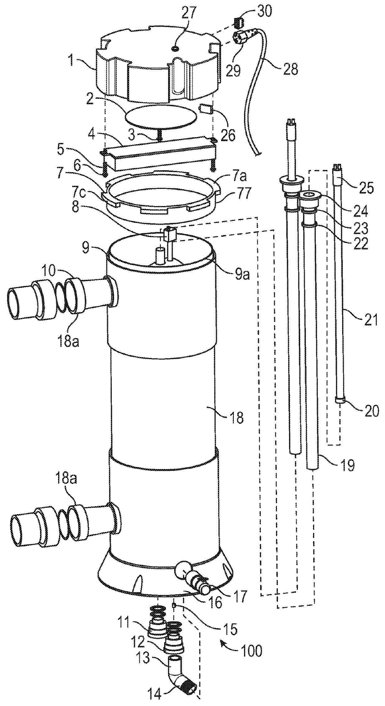
[0027]Referring to FIG. 1, a UV-light water sanitizer unit 100 of the present invention is shown. The unit includes a body tube 18 that is a water container or tank that can be generally cylindrical in shape as shown in this illustration. The body tube 18 further includes two ports 18a for use as water inlet and outlet for injecting water into the body tube, the other for exhausting water from the body tube. The body tube 18 is mounted on a mounting base 16 that rests on a surface and the upper end is capped with a body end cap 9.

[0028]An electronic ballast 4, and perhaps other electronics are isolated from ambient moisture and the water in the tank 18 by being situated above the body end cap 9 contained within a bonne...


PUM


Abstract

A ventilation ring for a UV water sanitizer unit that allows for adequate ventilation of heat generated by electronic components while sequestering those electronic components from water. The ring can also be made of a transparent or translucent material to allow a user to detect whether a UV lamp within the housing is operating. An improved nut for affixing a quartz tube within such a unit and improved design for draining the unit are also disclosed.

Description

STATEMENT OF RELATED APPLICATIONS[0001]This patent application claims priority on and the benefit of U.S. Provisional Patent Application No. 62 / 416,156 having a filing date of 1 Nov. 2016.COPYRIGHT NOTICE[0002]A portion of the disclosure of this patent document contains material which is subject to copyright protection. The copyright owner has no objection to the facsimile reproduction by anyone of the patent document or the patent disclosure as it appears in the United States Patent and Trademark Office patent file or records, but otherwise reserves all copyright rights whatsoever.BACKGROUND OF THE INVENTIONTechnical Field[0003]This invention relates to water sanitation treatment devices and more particularly to a method and apparatus for treating pool, spa or other bodies of water with UV light.Prior Art[0004]UV-light germicidal water treatment sanitization apparatus units are commonly used on swimming pools, spas and other reservoirs of water to control bacteria and lower depende...

Claims


Application Information

Patent Timeline
IPC IPC(8): C02F1/32C02F1/78
CPCC02F1/32C02F1/78C02F2103/42C02F2201/3226C02F1/325C02F2201/32C02F2201/3223
Inventor ROCHELLE, GARY P.
Owner CUSTOM MOLDED PROD
Why Eureka
Try Eureka