Aircraft fire seal structure and aircraft

a technology for aircraft and fire seals, applied in the direction of efficient propulsion technologies, machines/engines, transportation and packaging, etc., can solve the problems of difficult to obtain large elastic deformation amount, poor fire resistance of rubber seals containing silicone rubber or the like, and increased weight of fire seals, etc., to achieve excellent fire resistance, deterioration of fire seal performance, and small abrasion of walls

Active Publication Date: 2018-06-14
MITSUBISHI AIRCRAFT
View PDF0 Cites 16 Cited by
  • Summary
  • Abstract
  • Description
  • Claims
  • Application Information

AI Technical Summary

Benefits of technology

[0028]Each of the plurality of walls forming the labyrinth-like gap contains the refractory material such as a metal, excellent in durability to the flame as compared with a rubber material, and exists between the first partitioning member and the second partitioning member for the predetermined time under a situation where the plurality of walls are exposed to the flame. This makes it possible to prevent the flame inside the fire-prevention region from coming out of the fire-prevention region for the predetermined time without adding of a member that shields the plurality of walls from the flame.
[0029]The walls of the fire seal structure are not in contact with the cor

Problems solved by technology

The rubber seal containing silicone rubber or the like, however, is inferior in fire resistance to a metal material such as stainless steel.
If a member that shields the rubber seal from flame is necessary in order to delay a time until the fire seal performance is lost due to deterioration of elastic force of the rubber seal through exposure to flame and burning down of the rubber seal, the weight of the fire seal structure is increased.
When the elastic seal containing the metal material is used, the elastic seal is saved from being b

Method used


Image

  • Aircraft fire seal structure and aircraft
  • Aircraft fire seal structure and aircraft
  • Aircraft fire seal structure and aircraft

Examples


Embodiment Construction

[0041]Embodiments of the present invention are described with reference to accompanying drawings.

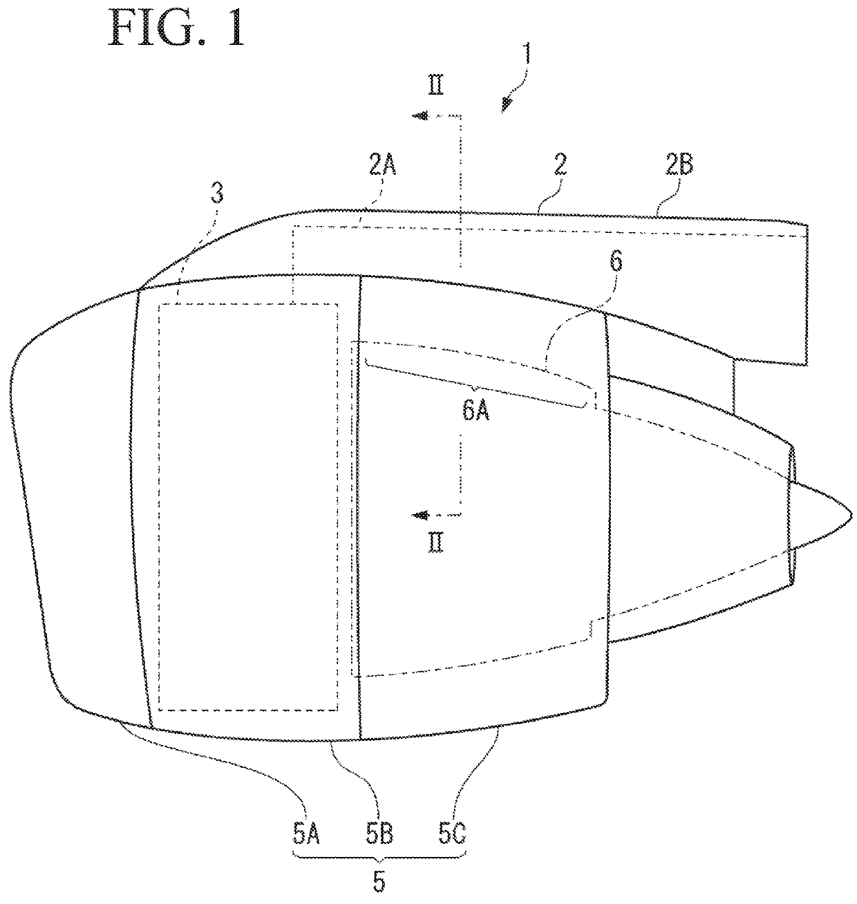
[0042]An engine 1 of an aircraft illustrated in FIG. 1 and FIG. 2 is supported to an unillustrated main wing by a pylon 2.

[0043]For example, in a case of a turbo fan engine, the engine 1 according to one or more embodiments includes a fan 3 (FIG. 1), an engine core (compressor and combustion chamber) 4 (FIG. 2) that is a main body of the engine 1, and a cylindrical engine nacelle 5 that surrounds the fan 3 and the engine core 4.

[0044]The pylon 2 includes a pylon main body 2A as a structure member, and a pylon fairing 2B that covers the pylon main body 2A. FIG. 1 illustrates only a front part of the pylon 2, and illustration of a rear part is omitted.

[0045]As illustrated in FIG. 1, the engine nacelle 5 includes an air inlet 5A that takes air into the fan 3, a fan cowl 5B that continues to a rear end of the air inlet 5A, and a thrust reverser cowl 5C that continues to a rear end of the fan...


PUM


Abstract

A fire seal structure prevents flame from coming out of a fire-prevention region of an aircraft. The fire seal structure includes: a plurality of walls including: a first wall provided on a first partitioning member; and a second wall provided on a second partitioning member. One of the plurality of walls is a spring wall that functions as a spring. The first and the second partitioning members define the fire-prevention region. The plurality of walls forms a labyrinth-shaped gap between the first and the second partitioning members. Each of the plurality of walls contains a refractory material and includes a front end part. When the first and the second partitioning members are stationary with respect to each other, the front end part is not in contact with another member, and the spring wall is disposed closest to a facing member, among the plurality of walls.

Description

BACKGROUND OF THE INVENTIONField of the Invention[0001]The present invention relates to a fire seal structure that prevents flame from coming out of a fire-prevention region of an aircraft.Description of the Related Art[0002]A fire-prevention region is designated around an ignition source from which flame may occur, such as an engine main body and an auxiliary power unit of an aircraft, and it is required to prevent the flame occurring inside the fire-prevention region from coming out of the fire-prevention region.[0003]For example, the fire-prevention region that confines the flame occurring from the engine main body (engine core) is designated inside an engine nacelle.[0004]When fire occurs from the engine main body, it is necessary to prevent the flame from coming through a gap between the engine nacelle and a pylon to blow off to outside. Accordingly, the gap between the engine nacelle and the pylon is sealed by an elastic seal (JP 2014-141202 A).[0005]The engine nacelle and the...

Claims


Application Information

Patent Timeline
IPC IPC(8): F02C7/25B64D27/26B64D29/00B64D45/00
CPCF02C7/25B64D27/26B64D29/00B64D45/00B64D2027/262B64D33/02F05D2220/323B64D2045/009B64C7/00B64D29/06F05D2240/14F05D2240/59Y02T50/60
Inventor TAKEUCHI, AKIRA
Owner MITSUBISHI AIRCRAFT
Why Eureka
Try Eureka