Apparatus and method for robust powered ethernet networks

Inactive Publication Date: 2018-06-14
PRATAP RANA J +2
View PDF5 Cites 5 Cited by
  • Summary
  • Abstract
  • Description
  • Claims
  • Application Information

AI Technical Summary

Benefits of technology

[0006]The present invention comprises a network device that is powered by a PSE switch or a POE power injector on an Ethernet port where the network device is configured to apply power to its other output ports where those other output ports act as PSE devices relative to other such devices or attached POE sensors. This approach facilita

Problems solved by technology

The use of relatively expensive cables to cover long distances can result in significant labor and material costs in the form of cabling, conduit, cable trays, etc.
For example, a surveillance camera placed on the outside of a building may not have a power drop nearby to provide the electrical power needed to operate the camera.
Those skilled in the art will recognize that a non-PD Ethernet device may be damaged or destroyed if POE voltage is applied to the non-PD Ethernet device.
As a consequence, the PSE does not apply voltage to the Ethernet cable unle

Method used


Image

  • Apparatus and method for robust powered ethernet networks
  • Apparatus and method for robust powered ethernet networks
  • Apparatus and method for robust powered ethernet networks

Examples


Embodiment Construction

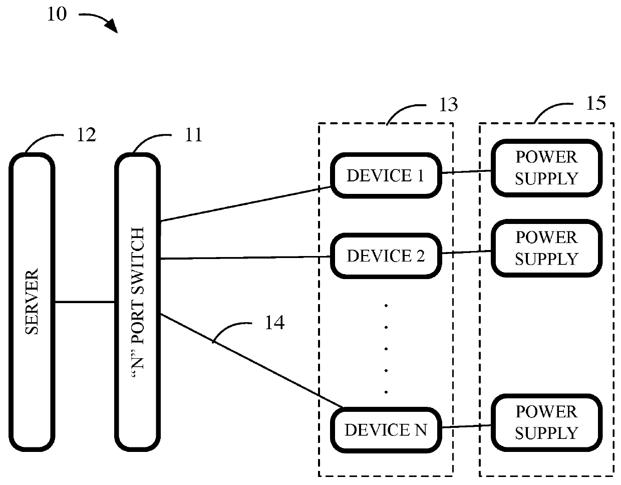
[0026]A network device provides a plurality of user configurable and controllable ports for supporting one or more powered devices and one or more power sources on a network, via a unique “n” port switch or similar hardware device. The network device disclosed herein allows each of the network ports to be functionally interchangeable in multiple application environments. Controller circuits and a logic unit automatically detect changes on the ports and reconfigure voltage and / or data paths so that the external devices connected to the switch continue to be able to communicate and provide or consume power. Since all ports function in a substantially identical manner, there is no need to label the ports as either input ports or output ports, where an input port would be connected to a provider of POE power and an output would be a consumer of POE power.

[0027]FIG. 1 through FIG. 5 illustrate cases of previously known solutions that can be used to provide context for better understandin...


PUM


Abstract

A network device provides a plurality of user configurable and controllable ports for supporting one or more powered devices and one or more power sources on a network, via a unique “n” port switch or similar hardware device. The network device disclosed herein allows each of the network ports to be functionally interchangeable in multiple application environments. Controller circuits and a logic unit or logic controller automatically detect changes on the ports and reconfigure voltage and/or data paths so that the external devices connected to the switch continue to be able to communicate and provide or consume power. Since all ports function in a substantially identical manner, there is no need to label the ports as either inputs or outputs, where an input port would be connected to a provider of POE power and an output would be a consumer of POE power.

Description

BACKGROUND OF THE INVENTION1. Technical Field[0001]The present invention relates to the field of power and data cabling and more specifically relates to cabling equipment for delivering power and data for certain applications using multiple sensors.2. Background Art[0002]In traditional Ethernet-networked sensor installations, a cable must generally be run from a centralized switch to each sensor in the network. Applications using multiple sensors, such as a security / monitoring system using multiple surveillance cameras, Ethernet-enabled thermostats, etc., will typically require multiple long cable runs of category 5 or category 7 cables. The use of relatively expensive cables to cover long distances can result in significant labor and material costs in the form of cabling, conduit, cable trays, etc.[0003]Another aspect of installing multiple sensors is the availability of power at each sensor. For example, a surveillance camera placed on the outside of a building may not have a powe...

Claims


Application Information

Patent Timeline
IPC IPC(8): H04L12/10G06F1/26
CPCH04L12/10G06F1/266G06F1/26
Inventor PRATAP, RANA J.MAJOR, JO S.GAISER, BRADLEY D.
Owner PRATAP RANA J
Why Eureka
Try Eureka